APPENDIX “B”
THOMSON POWER SYSTEMS
©
TS 870 SYSTEM VOLTAGE CHANGE
PROCEDURE
9087A - 198th Street, Langley, BC, Canada V1M 3B1 · Telephone (604) 888-0110
Email: info@thomsonps.com · www.thomsonps.com
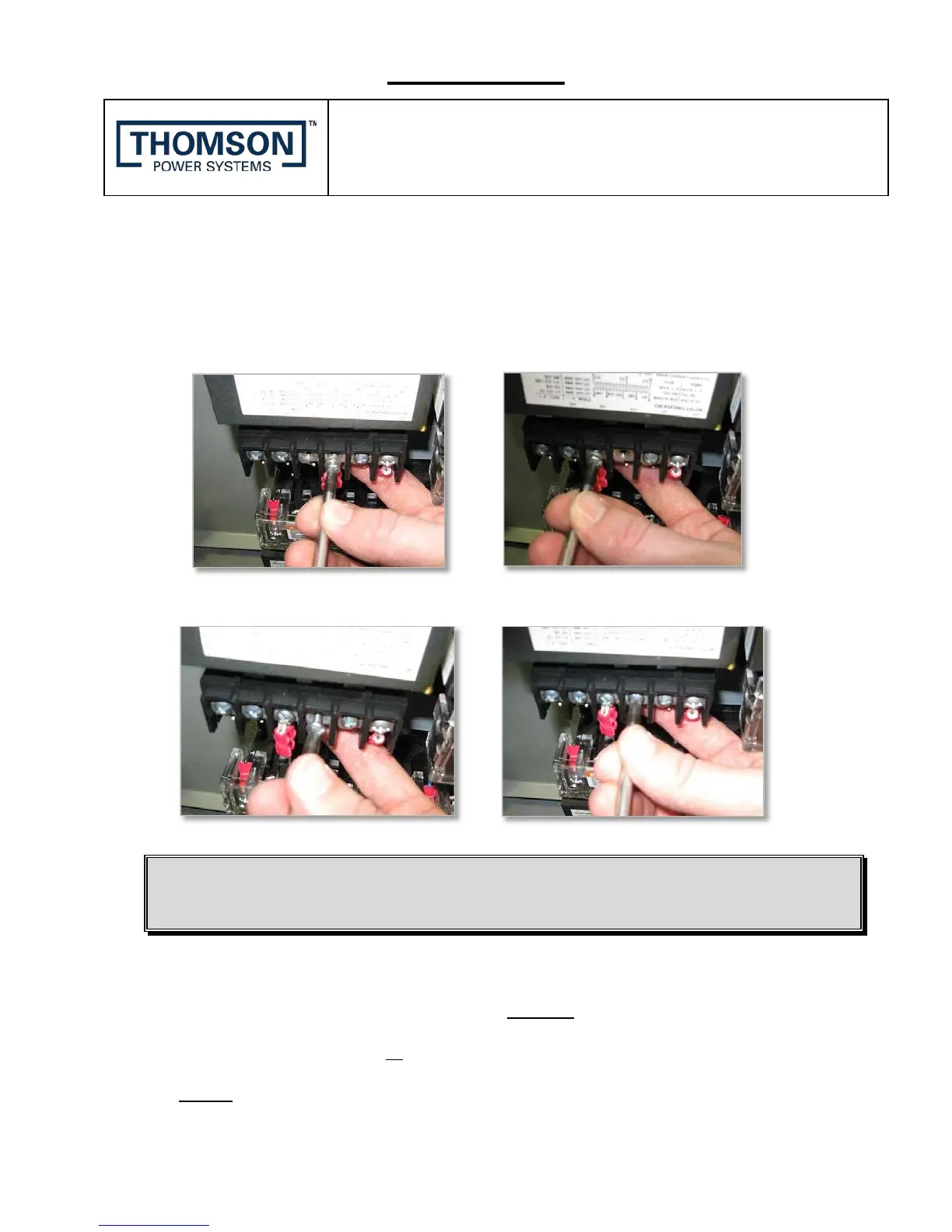
CAUTION: Brace PT terminal block with your hand when loosening or tightening ANY screws.
6. Remove the screw and red ring terminal connected to the incorrect (existing) PT voltage
terminal. Install the screw and red ring terminal to the new selected PT Tap Terminal based
on required voltage and tighten while supporting the terminal block. Make sure the ring
terminal is not misaligned or the PT cover will not fit back on.
7. Install the extra screw back onto the old PT location and tighten.
CAUTION
Confirm that PT screws are correctly tightened, and do not put strain
on the PT Tap wires.
8. Replace the PT cover. PT covers should 'snap' in place, confirm they are installed
correctly by gently "twisting" the PT cover. DO NOT use excessive force.
9. Repeat the steps 1 to 5 for all Potential Transformers.
NOTE: 2 to 3 PT’s will be installed in the Transfer Switch depending on the Model
type.
 Loading...