Rev D Mar 2020
Page 38
Chapter 6 Software Reference
Chapter 6 Software Reference
6.1 Introduction
This chapter gives an explanation of the parameters and settings accessed from the
APT software running on a PC.
6.2 GUI Panel
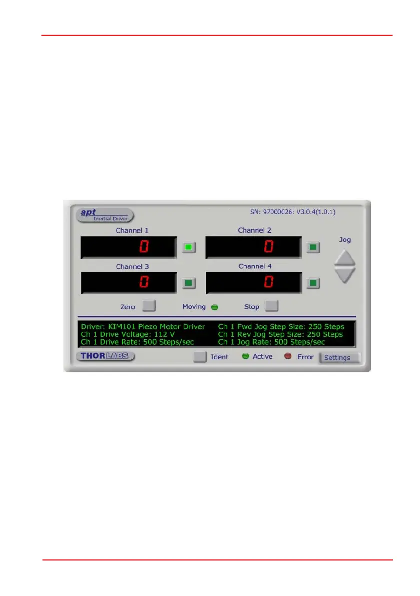
The following screen shot shows the graphical user interface (GUI) displayed when
accessing the Piezo Motor Driver K-Cube using the APTUser utility.
Fig. 6.1 Piezo Motor Driver K-Cube Software GUI
Note. The serial number of the Piezo Motor Driver K-Cube associated with the GUI
panel, the APT server version number, and the version number (in brackets) of the
embedded software running on the unit, are displayed in the top right hand corner.
This information should always be provided when requesting customer support.
Digital displays - Shows the position (drive pulses) of the motor associated with
the drive channel. The motor must be 'zeroed' before the display will show a
meaningful value, (i.e. the displayed position is relative to a physical datum).
The Channel 1 to 4 buttons allow each channel to be enabled and disabled
individually. When enabled, the channel being addressed is indicated by the LED
in the associated button. In some applications (e.g. if the actuators are fitted to a
2-axis mirror mount), it may be advantageous to move two axes at the same time
by moving the joystick diagonally. Channel pairs can be selected to move two
axes simulateously (CH1 and 2, and CH3 and 4).

 Loading...


