Open-Loop Piezo Controllers Chapter 8: Specifications
Page 22 Rev C, July 7, 2015
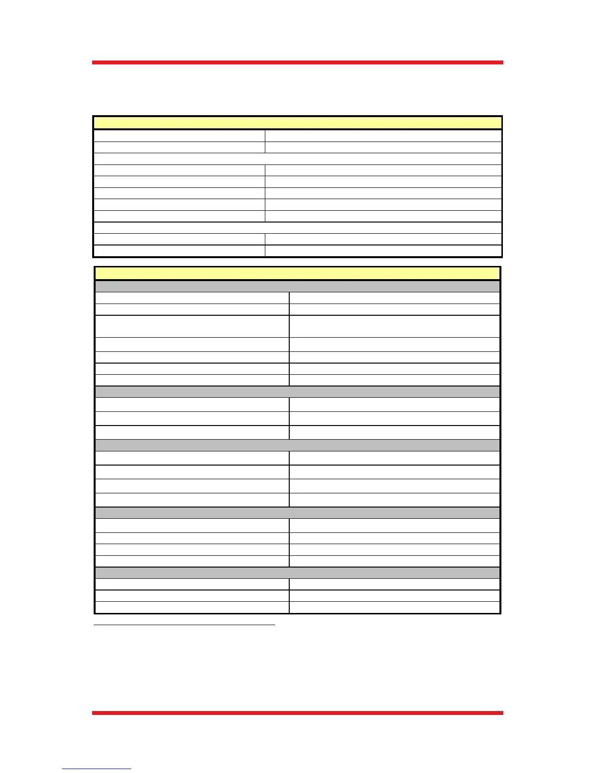
Chapter 8 Specifications
All specifications are for both MDT693B and MDT694B unless noted explicitly.
General Features
AC Input Voltage
100 - 240 VAC
AC Input Frequenc
50 – 60 Hz
AC Input Power (Max)
MDT693B
60 VA
MDT694B
30 VA
Operating Temperature
10 to 40 °C
Fuse Type
IEC60127-2/3 (250 VA, Slow Blow Type ‘T’)
Fuse Size
5 mm x 20 mm
Fuse Rating
MDT693B
600 mA
MDT694B
500 mA
1
The MDT693B and MDT694B were tested without an external load connected (1 nF output
impedance only). Adding a capacitive load, such as a piezo, will decrease the noise spec since the
capacitance will create a low-pass filter with the output resistance.
2
The Min Load Impedance represents the smallest allowable terminating resistance. Applying lower
impedances will cause the short-circuit protection to limit the output voltage. Continued use in this
mode will cause circuit degradation and eventual circuit failure.
3
Assume a ramp function is used. The bandwidth is load-dependent and requires calculation for a
more representative number. See Chapter 6, page13 for details.
Performance
Input/Output Specs
External Input Voltage
0 – 10 V
External Input Impedance
10 kΩ
Output Voltage
0 – 75, 0 – 100, or 0 - 150 VDC
(Limit Switch Dependent)
Output Current Limit (Max)
60 mA
Output Noise
1
1.5 mV
rms
(~9.9 mV
pp
)
Output Impedance (Max)
150 Ω, 1.0 nF
Min Load Impedance
2
2.5 kΩ
Output Voltage Range (Switch Selectable)
Voltage Limit Position (75 V)
0 – 75 VDC
Voltage Limit Position (100 V)
0 – 100 VDC
Voltage Limit Position (150 V)
0 – 150 VDC
External Input Gain
Voltage Limit Position (75 V)
7.5 V/V (±5%)
Voltage Limit Position (100 V)
10 V/V (±5%)
Voltage Limit Position (150 V)
15 V/V (±5%)
Scan Trim Gain Adjustment
80% to 120% of Master Scan Ext + Int
Bandwidth (-3 dB)
No Load, Small Signal
3
9 kHz
No Load, 150