Calibration & Measurement Module for OTKB/OTKBFM Chapter 4: Setup
TTN030035-D02 Page 8
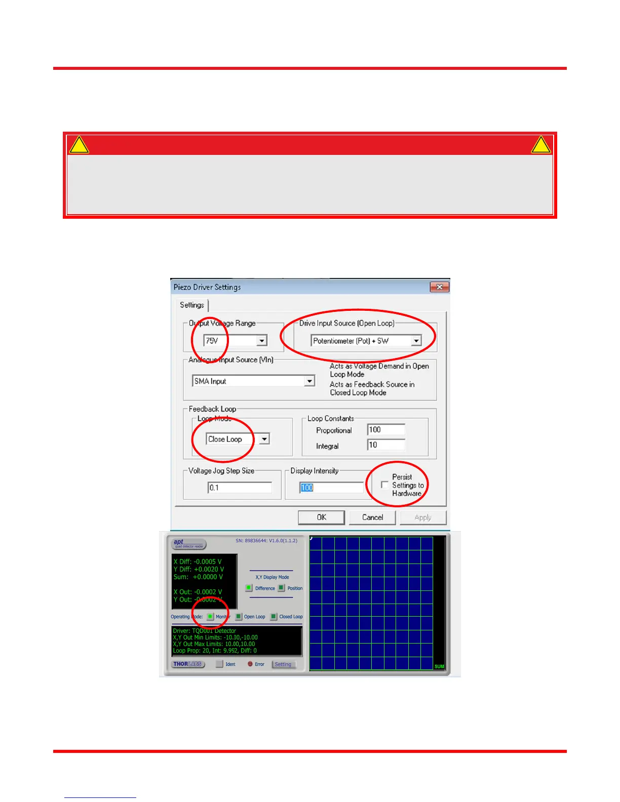
8. After the strain gauge controllers have been set to zero, you can set the piezo controllers to closed loop
mode. Select each of the piezo controller Setting windows and adjust the settings as shown in Figure 5.
Make sure that the “Persist Settings to Hardware” flag is set; this will save the configuration to the
controller’s EEPROM.
WARNING
If the Piezo Driver is switched to closed loop mode without a feedback signal applied, the piezo
drive voltage will ramp up to the maximum limit. If the limit is set to 75 V, a protective circuit limits
the voltage to 75 V. If 100 V or 150 V is selected, the output will ramp to 150 V. Using the standard
piezo stage supplied with the OTKB, the output voltage may not exceed 75 V. Higher voltages will
damage the stage.
9. For the PSD controller cube remember to set the operation mode to ‘Monitor’.
10. Close the APT User software.
Figure 5 Piezo Controller (KPZ101) Settings Window and PSD Aligner (KPA101) Settings Window
!
!