FUNCTION CHARACTERISTICS
41
NA011 - Manual - 05 - 2022
Automatic reclosure - 79
Preface
The automatic reclosure function is well-used on overhead lines (when faults are self-extinguish
after tripping of protection relays).
To activate the Auto-reclose function the CB state acquisition must be enabled!
Operation and settings
[1]
The following sequences may be selected:
• Rapid reclosure,
• Rapid reclosure + slow reclosure
• Rapid reclosure + slow reclosure followed by one or more delayed reclosures (1...5).
Starting of the automatic reclosing function can be raised by internal protective elements or exter-
nally by means binary input signals (eg: external protection device contacts or operating switches).
The following logics may be set (binary input IN3 allocation):
• External trip; activation command (pulse),
• Enabling; activation command (On = Enable).
The element may be enabled or disabled by setting ON the 79 Enable parameter available inside
the Set \ AutoReclose-79 menu.
The following output functions may be drive the output relays:
• CB reclosing command (79 Close); it is needful for the auto reclosure function.
• Cycle in progress (79 Run).
• Reclosure fail (79 Fail).
The following timers are provided:
• t
rdt
Rapid reclosure dead time
• t
sdt
Slow reclosure dead time
• t
r
Reclaim time
• t
d
Slow reclosure fault discrimination time
Note 1 The CB state acquisition must be enabled; if CB check = None the 79 function is disabled
all-F79.ai
79 Enable
52a, 52b, 52a&52b
79 Trigger
79-Close
79-Run
79
79-Fail
Trip I>
&
Trip I>
Trip I>>
&
Trip I>>
Trip IE>
&
Trip IE>
Trip I>>
&
Trip I>>
Trip IE>>
&
Trip IE>>
Trip ProtExt
&
Trip Remote
≥ 1
Binary input INx
T 0
Logic
INx
t
ON
INx
t
ON
INx
t
OFF
T0
n.o.
n.c.
INx
t
OFF
Binary input INx
T 0
Logic
INx
t
ON
INx
t
ON
INx
t
OFF
T0
n.o.
n.c.
INx
t
OFF
Binary input INx
T 0
Logic
INx
t
ON
INx
t
ON
INx
t
OFF
T0
n.o.
n.c.
INx
t
OFF
Binary input INx
T 0
Logic
INx
t
ON
INx
t
ON
INx
t
OFF
T0
n.o.
n.c.
INx
t
OFF
79 Remote
Block2 IPh/IE
ModeBLIN1
T 0
t
B-Iph
50-51S2_BL-diagram.ai
≥ 1
≥ 1
≥ 1
≥ 1
≥ 1
t
B-Iph
t
B-IE
BLK1I>>
&
&
BLK2IN I>>
&
&
Enable (ON≡ Enable)
I>>BLK1
Block2 input enable (ON≡ Enable)
Pilot wire input
Pilot wire output
&
I>>BLK2IN
Block1
BLK2IN-Iph
Start I>>
Trip I>>
Iph Block2
IE Block2
IE/Iph Block2
BLK2IN-IE
tB timeout
Block2 input
Block1
FROM EARTH FAULT PROTECTIONS
FROM ANY PROTECTIONS
OFF
ON IPh
ON IPh/IE
ON IE
BLIN1
Block1
T 0
t
B-IE
Block2 IE
Block1, Block2
TRIPPING MATRIX
(LED+RELAYS)
TRIPPING MATRIX
(LED+RELAYS)
≥ 1
≥ 1
ModeBLOUT1
A
B
C
D
BLOUT1
Block2 output
≥ 1
≥ 1
t
F-IPh
t
F-IPh/IE
t
F-IE
ST-Iph BLK2
ST-IE BLK2
&
Block2 output
(ON≡ Enable)
I>>BLK2OUT
Start I>>
≥ 1
T 0
t
F-IPh/IE
T 0
t
F-IPh
T 0
t
F-IE
I>> Blk2 OUT
I> Blk2 OUT
I>>> Blk2 OUT
I
E
>> Blk2 OUT
I
E
> Blk2 OUT
I
E
>>> Blk2 OUT
BLK2OUT-Iph
BLK2OUT-Iph/IE
BLK2OUT-IE
A = OFF
B = ON IPh
C = ON IPh/IE
D = ON IE
BLK2OUT-IPh-K
BLK2OUT-IPh-L
BLK2OUT-IPh/IE-K
BLK2OUT-IPh/IE-L
BLK2OUT-IE-K
BLK2OUT-IE-L
tB-K
tB-L
Phase overcurrent (50/51) - Logic diagram of the blocking signals concerning the second element (I>>)
CB check
IN3 select
79 Enable 79 Mode 79 MC-td-EN 79 MO-RES
N.DAR
t
rdt
t
sdt
t
r
t
d
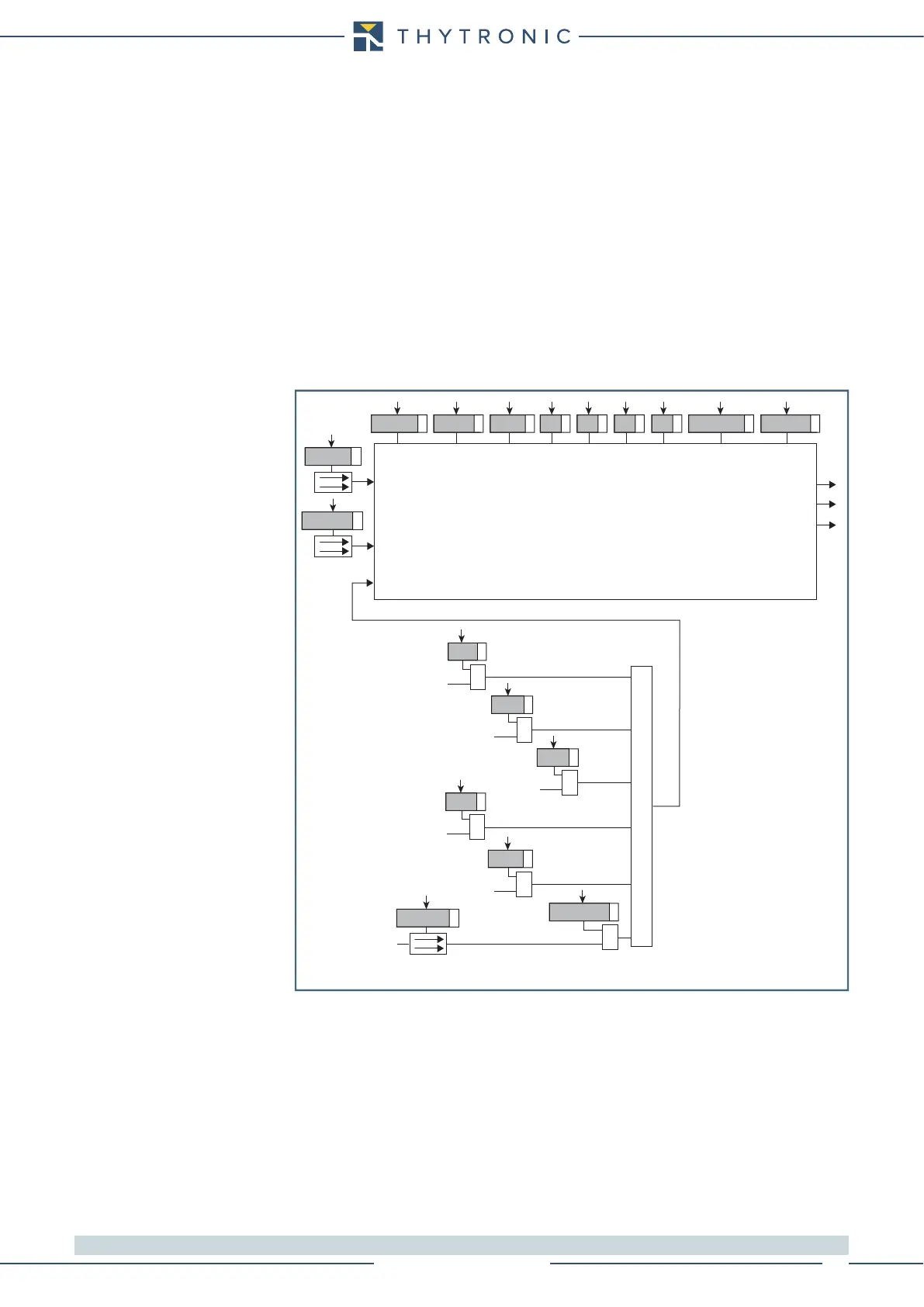
General logic diagram of the automatic reclose function - 79