FUNCTION CHARACTERISTICS
36
NA011 - Manual - 05 - 2022
Residual overcurrent - 50N/51N
Preface
The residual current is:
• Measured for NA011#xxx2 and NA011#xxx3 versions from one residual current input with second-
ary nominal current selectable at 1 A or 5 A through DIP-switches or,
Calculated for NA011#xxx0 and NA011#xxx1 versions by the vector sum of the three phase currents,
measured by three 1A or 5A CTs or by three LPCT type sensors.
Two operation thresholds, independently adjustable (I
E
>, I
E
>> with adjustable delay (t
E
>,
t
E
>>) are available; they may be programmed with definite or inverse time according the IEC, ANSI/
IEEE or I2T standard curves.
Operation and settings
The residual fundamental frequency current) is compared with the setting value. Current above the
associated pickup value is detected and a start is issued. After expiry of the associated operate
time a trip command is issued; if instead the current drops below the threshold, the element it is
restored.
The thresholds (I
E
> and I
E
>>) may be programmed with definite or inverse time according the follow-
ing characteristic curves:
• Standard Inverse Time (IEC 255-3/BS142 type A or SIT): t = 0.14 · t
E
>
inv
/ [(I
E
/I
E
>
inv
)
0.02
- 1]
• Very Inverse Time (IEC 255-3/BS142 type B or VIT): t = 13.5 · t
E
>
inv
/ [(I
E
/I
E
>
inv
) - 1]
• Extremely Inverse Time (IEC 255-3/BS142 type C or EIT): t = 80 · t
E
>
inv
/ [(I
E
/I
E
>
inv
)
2
- 1]
• Moderately Inverse (ANSI/IEEE type MI): t = t
E
>
inv
· {0.01 / [(I
E
/I
E
>
inv
)
0.02
- 1] + 0.023}
• Very Inverse (ANSI/IEEE type VI): t = t
E
>
inv
· {3.922 / [(I
E
/I
E
>
inv
)
2
- 1] + 0.098}
• Extremely Inverse (ANSI/IEEE type EI): t = t
E
>
inv
· {5.64 / [(I
E
/I
E
>
inv
)
2
- 1] + 0.024}
• I-squared-t (I
2
t = K): t = 16 · t
E
>
inv
/ (I
E
/I
E
>
inv
)
2
where:
t: operate time
I
E
>: pickup value
t
E
>
inv
: operate time setting
For all inverse time characteristics, following data applies:
• Asymptotic reference value (minimum pickup value): 1.1 I
E
>
• Minimum operate time: 0.1 s
• Range where the equation is valid:
[1]
1.1 ≤ I
E
/I
E
>
inv
≤ 20
• If I
E
>
inv
pickup ≥ 2.5 I
En
, the upper limit is 10 I
En
For all definite time elements the upper limit for measuring is 10 I
En
for version with CTs inputs and
35 I
n
for version with LPCTs inputs.
All elements can be enabled or disabled by setting the relative start and/or trip output to a selectable
relay inside the Set \ Relays menu.
For each threshold a reset time can be set (t
E>RES
, t
E>>RES
) useful to reduce the clearing time for
intermittent faults.
Note 1 When the input value is more than 20 times the set point , the operate time is limited to the value corresponding to 20 times the set point
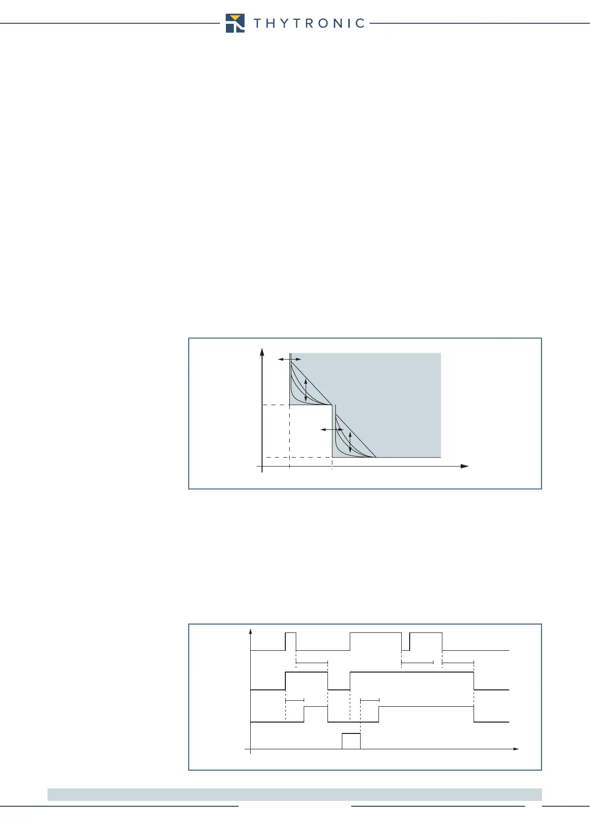
General operation time characteristic for the residual overcurrent elements - 50N/51N
I
E
I
E
>>
t
E
>
t
E
>>
I
E
>
t
TRIP
Timers-F50N-51N.ai
IE> element residual overcurrent (50N/51N) - Timers
IE> Start
IE> Trip
t
E>
t
E>
RESET
INPUT
t
E>RES
t
E>RES
t
E>RES
t