APPENDIX
88
NA011 - Manual - 05 - 2022
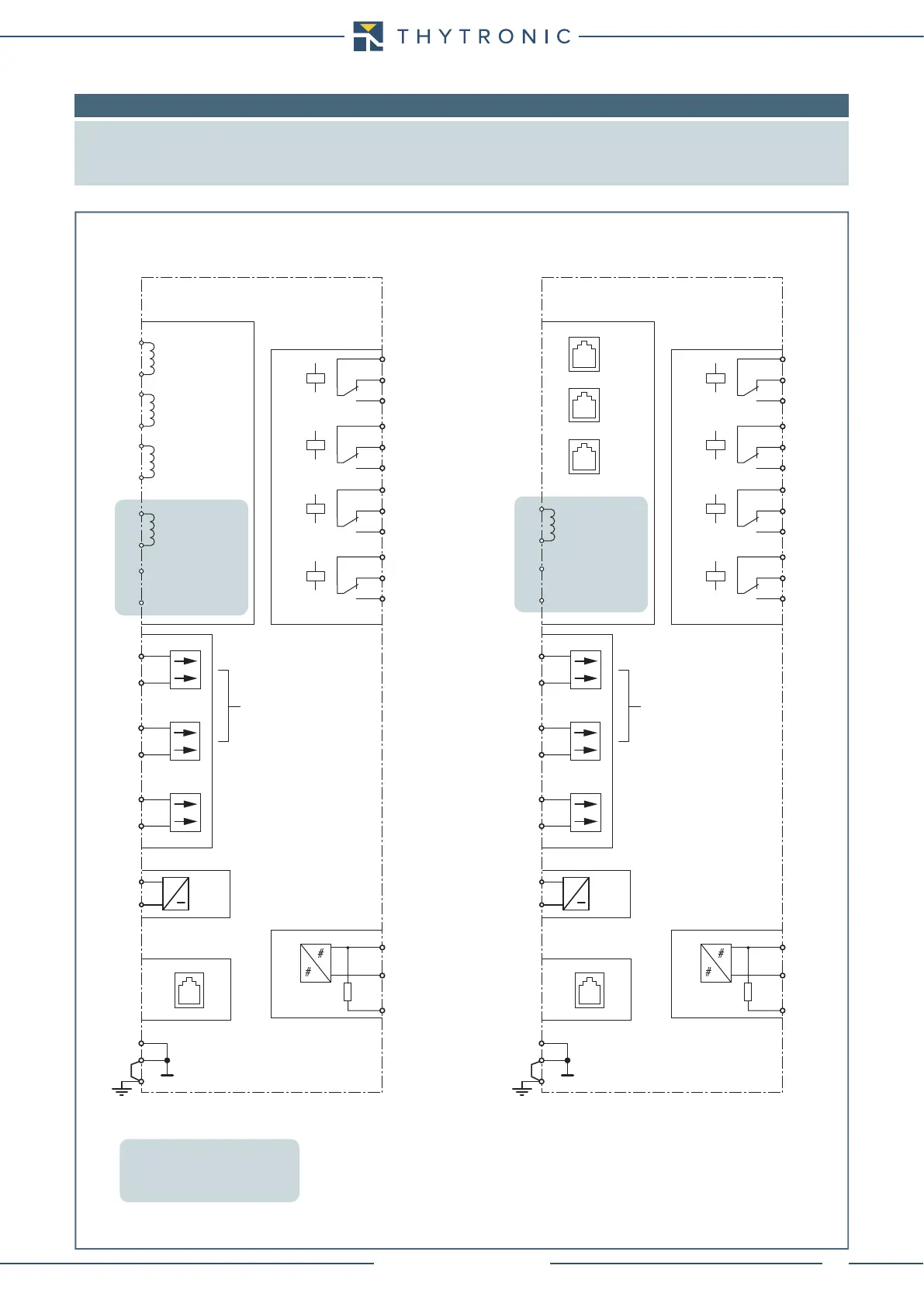
8.4 APPENDIX B1 - I/O Diagram
Note: Some typical connection diagram are shown.
All diagram must be considered just as example; they cannot be comprehensive for real applications.
For all diagrams the output contacts are shown in de-energized state for standard reference.
The residual current input (pin C7-C8) is available on NA011#xxx2 and NA011#xxx3 versions
NA016-I-O.ai
Input-output circuits
alternative versions
to be selected when ordering
Traditional CT input circuits Low powerCT input circuits (LPCTs)
NA011
C1
I
L1
I
L2
I
L3
I
E
CURRENT INPUTS
C2
C3
C4
C5
C6
C7
C8
C7
C8
RS232
FRONT PANEL
A13
IN1
IN2
IN3
A14
A15
A16
A17
A18
OUTPUT RELAYS
A4
A6
A5
K2
A2
A1
A3
K1
A11
A12
A10
K4
A9
A8
A7
K3
U
AUX
A19
≅
A20
A22
A21
B-
E1
RS485
1
2
3
120Ω
A+
CIrcuit Breaker
Position
79 IN3 Select
CIrcuit Breaker
Position
79 IN3 Select
NA011
I
E
CURRENT INPUTS
C7
C8
C7
C8
RS232
FRONT PANEL
A13
IN1
IN2
IN3
A14
A15
A16
A17
A18
OUTPUT RELAYS
A9
A8
A7
K2
A5
A4
A6
K1
A11
A12
A10
K4
A3
A2
A1
K3
U
AUX
A19
≅
A20
A22
A21
B-
E1
RS485
1
2
3
120Ω
A+
L1
L2
L3
NA011#xxx2
NA011#xxx0
NA011#xxx3
NA011#xxx1