MEASURES, LOGIC STATES AND COUNTERS
48
NA011 - Manual - 05 - 2022
• Analog channels (1...4) allocation.
• Digital channels allocation (output relay and/or binary inputs).
• Trigger setup; the information storage starts when a state transition on the selected signal occurs.
(protective element start and/or trip, output relay and/or binary input switching).
Example 1
With the following setting:
• Analog channel 1: i
L1
• Analog channel 2: i
L2
• Analog channel 3: i
L3
• Analog channel 4: i
L4
• Digital channel: K1
• Pre-trigger: 1 T (20 ms)
the stored record length of the two records with f = 50 Hz is 240 ms
Example 2
With the following setting:
• Analog channel 1: i
L1
• Analog channel 2: -
• Analog channel 3: -
• Analog channel 4: -
• Digital channel: K1
• Pre-trigger: 1 T (20 ms)
the stored record length of the two records with f = 50 Hz is 640 ms
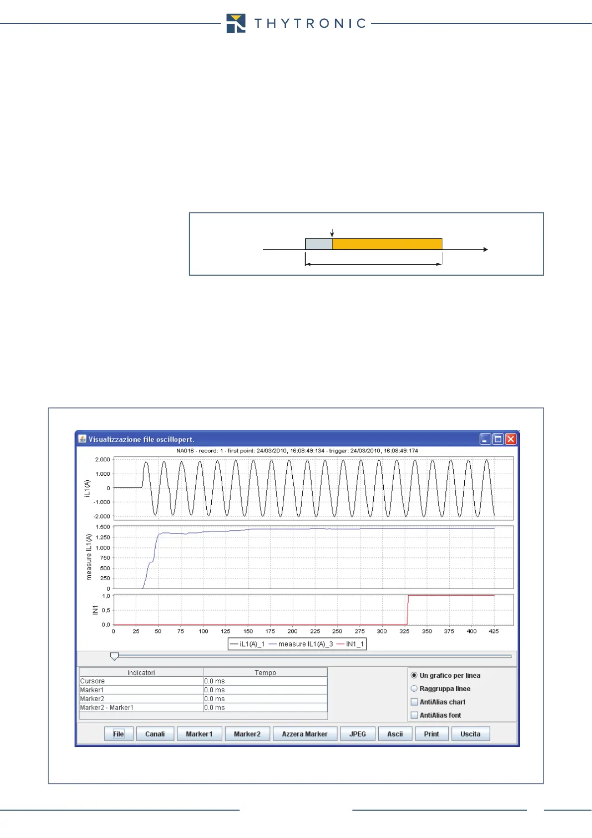
trigger.ai
Trigger
Time
240 ms
1 T
20 ms
oscillo-phase.ai
Oscillographic recorder example