FUNCTION CHARACTERISTICS
17
NA016 - Manual - 05 - 2022
4 FUNCTION CHARACTERISTICS4 FUNCTION CHARACTERISTICS
4.1 HARDWARE DESCRIPTION
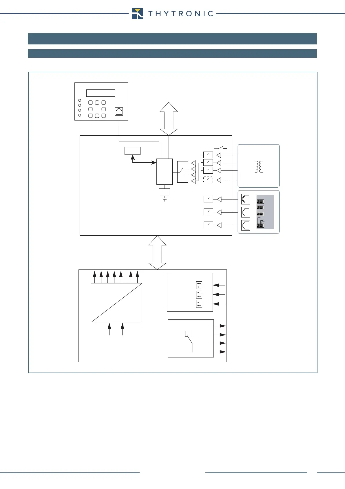
The following figure illustrates the basic structure of the relay.
Printed boards hold the circuit components arranged according to a modular allocation of the main
functions.
Power supply board
All the components necessary for conversion and stabilization functions are present.
Two versions are envisaged suited to the input range 24...230 V.
The circuit provides stabilized voltages of +5 V and -5 V, required for the analogue measurement and
+3.3 V for supplying the digital circuits.
The circuit board additionally comprises:
INPUT CIRCUITS:
• Three binary input circuits,
The logical input circuits and the block circuits include photo-couplers which provide for galvanic
separation.
OUTPUT CIRCUITS:
• Four output relays (k1...K4).
hw.ai
RTC
CPU BOARD
POWER SUPPLY BOARD
INPUT MODULE
CTs
DSP
1A/5A
≈
≈
≈
≈
EEprom
RS485
RELAYS
K1...K4
Output contacts
RS232
MMI
LCD
LEDs
BINARY INPUTS
IN1
Input
IN2
IN3
POWER SUPPLY
+5 V
+10 V
0 V
+24 V
-10 V
POWER FAIL
RESET
Uaux
≈
≈
≈
LPCTs CURRENT INPUTS
I
L1
I
L2
I
L3
L1
L2
SettingLPCT
800 A
400 A
200 A
100 A
50 A
L3
In=50...1250A