INSTALLATION
43
NA016 - Manual - 05 - 2022
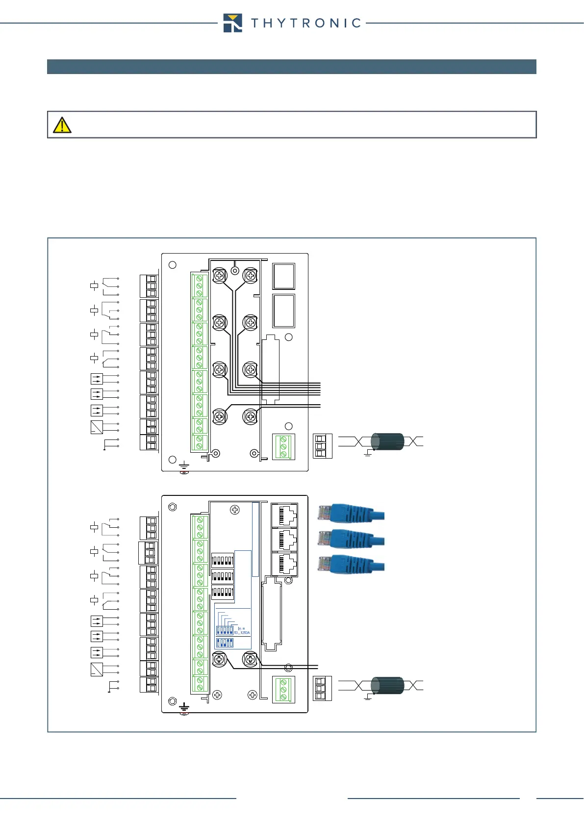
6.3 ELECTRICAL CONNECTIONS
Electrical connections should be made by referring to the connection diagram; in cases where cer-
tain of the circuits (communication, block, or others) are not used, the relevant connections must
remain open. Examples of connection diagrams are reported on Appendix to this manual.
For the A1...A22 connections and E1...E3 (RS485), screw terminals with following characteristics are
available:
• Nominal cross section: 0.14...2.5 mm
2
(AWG 26...16) for single conductor
da 0.14 a 0.75 mm
2
for two conductors with same cross section
• Tightening torque: 0.5-0.6 Nm
• Stripping length: 8 mm
The connections to the current signal inputs C1...C8 can be made by ring lugs suitable for M4 screws
and an insulating panel covering the terminals may be mounted for safety purposes.
Devices must be installed by qualified personnel only. No liability is accepted from Thytronic due to improper use.
CAUTION
Amperometric phase inputs from traditional CTs
Amperometric input from residual CT
Amperometric input from residual CT
Amperometric phase inputs from LPCTs
RS485
1 2 3
B-
A+
U
AUX
≅
A4
A5
K2
A2
A1
A3
K1
A11
A10
A12
K4
A13
A14
A9
A7
A8
A6
K3
A15
A16
A17
A18
A19
IN1
A20
A21
A22
IN2
IN3
F1
D1
RX
TX
F2
F3
F4
F5
A1
A2
A3
A4
A5
A6
A7
A8
A9
A10
A11
A12
A13
A14
A15
A16
A17
A18
A19
A20
A21
A22
B1
B2
B3
B4
B5
B6
B7
B8
C1 C2
C4
C3
C5 C6
C7 C8
E1
3
1
2
RS485
1 2 3
B-
A+
C7 C8
F1
D1
RX
TX
F2
F3
F4
F5
A1
A2
A3
A4
A5
A6
A7
A8
A9
A10
A11
A12
A13
A14
A15
A16
A17
A18
A19
A20
A21
A22
B1
B2
B3
B4
B5
B6
B7
B8
E1
3
1
2
L1
(100+200)
300A
EX. In =
LPCT
50
L3
200
400
100
800
Setting
L2
L3
L2
L1
1 2 3 4 5
1 2 3 4 5
1 2 3 4 5
U
AUX
≅
A5
A4
A6
K1
A11
A10
A12
K4
A13
A14
A3
A1
A2
K3
A9
A7
A8
K2
A15
A16
A17
A18
A19
IN1
A20
A21
A22
IN2
IN3