FUNCTION CHARACTERISTICS
34
NA016 - Manual - 05 - 2022
The fault condition of the trip circuit is detected by binary input power down.
With healthy circuit and TRIP contact closed, the binary input is feed across the 52a path (CB closed)
or across the resistor R and 52b path (CB open).
When the TRIP contact turns ON, the binary input becomes short-circuited; to avoid untimely opera-
tions the previous condition are checked every 80 ms and the output is issued after a 40 s delay in
order to allow the fault clearing and the consequent reset of the TRIP protection.
Outputs are reset to zero after 6 s from the TRIP contact open.
[1]
How to calculate resistance
Both the following conditions must be filled:
1) The circuit breaker coil must no be powered when the CB is open and an open command is is-
sued;
2) The binary input is energized when the trip contact open.
1) If the circuit breaker is just open an unnecessary excitation must be avoided; the most critical
event arises when the TRIP contact is closed (e.g. manual or test command), so with minimal
series resistance. To avoid an unwanted excitation the series resistance must be higher than a
minimum value defined as:
R
min
= R
TC
· (U
AUX
- U
TCmin
) / U
TCmin
where:
U
TCmin
: minimum coil excitation voltage
U
AUX
: auxiliary voltage
R
TC
: coil resistance
2) To energize the binary input circuit when the TRIP contact and CB open, the series resistance
must be lowerer than a maximum value defined as:
R
max
= [(U
AUX
- U
DIGmin
) / I
DIG
] - R
TC
where:
U
DIGmin
: minimum binary input excitation voltage (18 V)
U
AUX
: auxiliary voltage
R
TC
: coil resistance
I
DIG
: binary input excitation current (0.003 A)
To satisfy the above requirements, the R value must be chosen between the R
min
and R
max
values;
typically the normalized value nearest the arithmetic mean:
R = (R
min
+ R
max
) / 2
The power dissipated by the R resistor is:
P
R
= R
· I
2
= R
· [U
AUX
/ (R + R
TC
)]
2
Example
U
AUX
= 110 Vcc (auxiliary voltage)
P
TC
= 50 W (coil power)
R
TC
= U
AUX
2
/ P
TC
= 242 Ω (coil resistance)
U
TCmin
= 77 V (minimum coil excitation voltage = 70% U
AUX
)
U
DIGmin
= 18 V (minimum binary input excitation voltage)
I
DIG
= 0.003 A (binary input excitation current)
R
min
= R
TC
· (U
AUX
- U
TCmin
) / U
TCmin
= 242 · (110 - 77) / 77 = 103.7 Ω
R
max
= [(U
AUX
- U
DIGmin
) / I
DIG
] - R
TC
= [(110 - 18) / 0.003] - 103.7 = 30563 Ω
R = (R
min
+ R
max
) / 2 = (103.7 + 30563) / 2 = 15333 Ω ~ 15 k Ω
P
R
(Power dissipated by the R resistor) = U
AUX
2
/R = 110
2
/ 15000 = 0.8 W
P
R
= R
· I
2
= R
· [U
AUX
/ (R + R
TC
)]
2
Note 1 The trip contact (TRIP) of the protection relays must be set with automatic reset (No-latched operating mode).
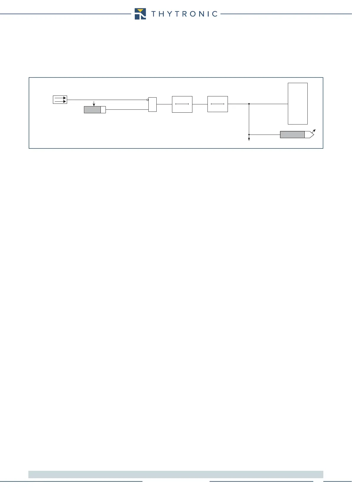
Fun-74TCS1.ai
0
40 s
T
0
6 s
T
&
Enable (ON≡ Enable)
74TCS
TRIPPING MATRIX
(LED+RELAYS)
IN3
Trip 74TCS
Relay Trip 74TCS
LED Trip 74TCS
Trip 74TCS
Logic diagram concerning the Trip Circuit Supervision - 74TCS