106
FUNCTION CHARACTERISTICS
— Directional active overpower - 32P
Preface
The active power is calculated as:
P=U
L1
I
L1
cosf
L1
+ U
L2
I
L2
cosf
L2
+U
L3
I
L3
cosf
L3
where:
• U
L1
, U
L2
, U
L3
are the fundamental components of the phase-to-neutral voltages
• I
L1
, I
L2
, I
L3
are the fundamental components of the phase currents
• cosf
L1
, cosf
L2
, cosf
L3
are the phase power factors
f
L1
, f
L2
, f
L3
, are the displacement angles of phase currents I
L1
, I
L2
, I
L3
respect to the phase voltages
U
L1
, U
L2
, U
L3
, (positive when lag currents compared the phase voltages).
Operation and settings
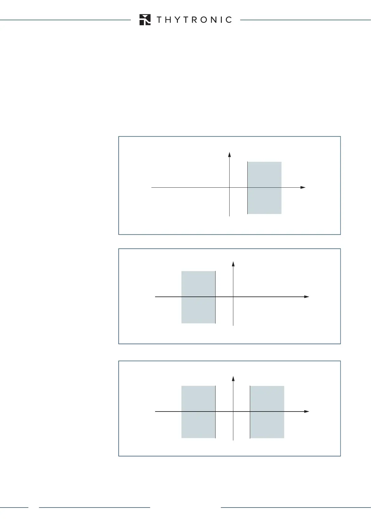
The element is enabled for start and trip on the base of the direction setting for the two independent-
ly programmable thresholds.
P1> Tripping direction:
PForward:
P1> Tripping direction: PReverse:
P1> Tripping direction: PForwaed/Reverse:
P
Q
TRIP
P
1
>
P1> Tripping direction: P Forward:
General operation time characteristic for the directional active overpower element - 32P
P
Q
Caratteristica d’intervento relativa alla soglia P1> della funzione di Massima potenza attiva
direzionale (32P)
Impostazione Direzione d’intervento: P Inversa
TRIP
P
1
>
P
Q
TRIP
P
1
>
TRIP
P
1
>
P1> Tripping direction: P Forward/Reverse:
General operation time characteristic for the directional active overpower element - 32P
XMR-D EQUIPMENT MANUAL
Ed. 2.9 - 02/2021