64
FUNCTION CHARACTERISTICS
— Binary inputs
According to hardware preset up to 53 binary inputs are available (MINIMUM equipment 0).
The dry inputs must be powered with an external voltage, (usually the auxiliary power supply).
The connections are shown in the schematic diagrams.
The following settings can be used to configure each input inside the Set \ Board 1(2) inputs \ Binary
input IN1-1...(IN1-x):
• Logic Active-ON (activated when powered), or Active-OFF (activated when power is turned off).
• ON Timer (OFF-to-ON time delay IN1-1 tON...IN1-X tON, INy-1 tON...INy-X tON) and OFF Timer (ON-
to-OFF time delay IN1-1 tOFF...IN1-X tOFF, INy-1 tOFF...INy-X tOFF).
• Binary input allocation.
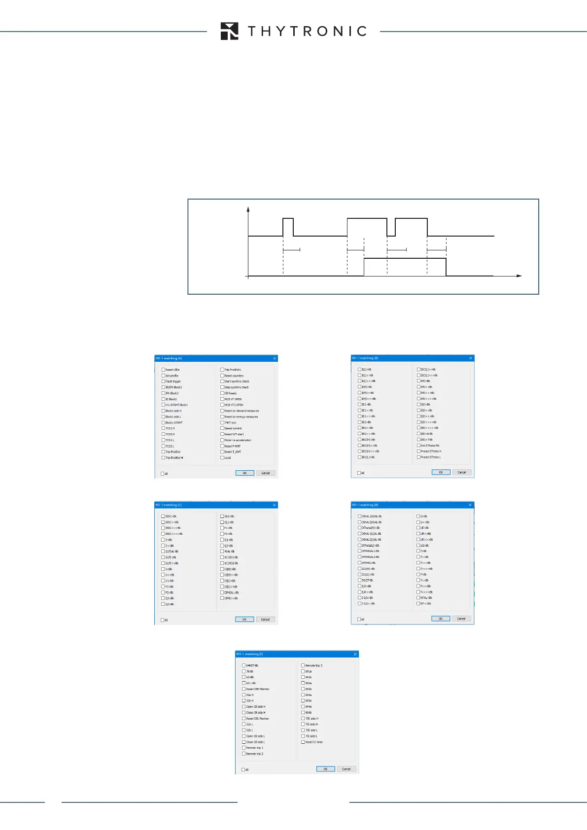
Adjustable debounce timer allows any transient to decay avoiding false activation of the input; the
positive transition is acquired if the input is permanently high for a time interval longer than the t
ON
setting delay; similarly for the negative transitions, the negative transition is acquired if the input is
permanently high for a time interval longer than the t
OFF
setting delay.
In the diagram, INTERNAL STATE represents the logical state of the binary input used in the following
processing. Each binary input may be matched to one of the following default functions.
BINARY INPUT
INTERNAL STATE
t
ON
t
ON
t
OFF
t
OFF
t
binary-timers.ai
XMR-D EQUIPMENT MANUAL
Ed. 2.9 - 02/2021