186
FUNCTION CHARACTERISTICS
For all inverse time characteristics, following data applies:
• Asymptotic reference value (minimum pickup value): 1.1 I
E1
>
• Minimum operate time: 0.1 s
• Range where the equation is valid:
[1]
1.1 ≤ I
E1
/I
E1
>
inv
≤ 20
• If I
E1
>
inv
pickup ≥ 2.5 I
E1n
, the upper limit is 10 I
E1n
For all definite time elements the upper limit for measuring is 10 I
E1n
.
All residual overcurrent elements can be enabled or disabled by setting ON or OFF the IE1>
Enable, IE1>>Enableand/or IE1>>>Enableparameters inside the Set \ Profile A (or B) \ Re-
sidual overcurrent-50N.1/51N.1 \ IE1> Element (IE1>> Element, IE1>>> Element) \ Setpoints menus.
The first overcurrent element can be programmed with definite or inverse time characteristic by
setting the IE1>Curve parameter (
DEFINITE, IEC/BS A, IEC/BS B, IEC/BS C, ANSI/IEE
MI,ANSI/IEEVI,ANSI/IEEEI,EM) available inside the Set \ Profile A (or B) \ Residual overcur-
rent-50N.1/51N.1 \ IE1> Element \ Setpoints menu.
The trip of IE1> element may be inhibited by the start of the second and/or third element (IE1>>,
IE1>>>) by setting ON the Disable IE1> by start IE1>>, Disable IE1> by start IE1>>> (IE1>di-
sbyIE1>>,IE1>disbyIE1>>>) parameters available inside the Set \Profile A (or B) \ Residual
overcurrent-50N.1/51N.1 \ IE1>> Element (IE1>>> Element) \ Setpoints menus.
Similarly the trip of the I
E
>> element may be inhibited by start of the third element (I
E
>>>) by setting
ON the Disable IE>> by start IE>>> (IE>>disbyIE>>>) parameter available inside the Set \ Profile
A (or B) \ Residual overcurrent-50N.1/51N.1 \ IE1>>> Element \ Setpoints menu.
All the named parameters can be set separately for Profile A and Profile B
An adjustable reset time delay is provided for every threshold t
E1>RES
, t
E1>>RES
, t
E1>>>RES
).
Breaker failure (BF)
Each thresholds (IE1>, IE1>>, IE1>>>) can be associated to BF (H) and BF (L) protection by activating
the relative parameter in the matrices “Selection of function tripping for BF (H)” or “Selection of
function tripping for BF (L)” in relevant BF menus
[2]
:
• Set \ Profile A (or B) \ Breaker failure - BF side H
• Set \ Profile A (or B) \ Breaker failure - BF side L
Note 1 When the input value is more than 20 times the set point , the operate time is limited to the value corresponding to 20 times the set point
Note 2 The common settings concerning the Breaker failure protection are adjustable inside the Breaker Failure - BF menu.
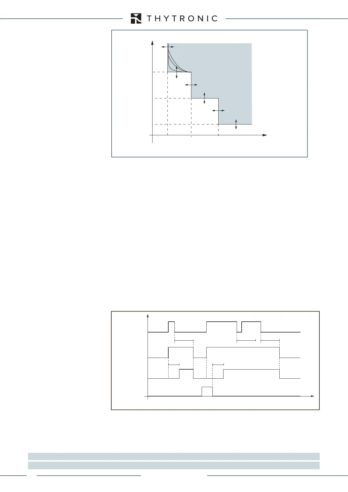
t-int-F50N-51N.ai
I
E1
I
E1
>> I
E1
>>>
t
E1
>
t
E1
>>
t
E1
>>>
I
E1
>
t
General operation time characteristic for the residual overcurrent elements - 50N.1/51N.1
TRIP
Timers-F50N-51N.ai
IE1> Start
IE1> Trip
t
E1>
t
E1>
RESET
INPUT
t
E1>RES
t
E1>RES
t
E1>RES
t
IE> element residual overcurrent (50N.1/51N.1) - Timers
XMR-D EQUIPMENT MANUAL
Ed. 2.9 - 02/2021