2 Installation
2.1 Location
To receive GPS signals the Time Server's antenna must be located in a location where it can “see” the
sky. The GPS module itself is highly sensitive and able to “see” the GPS satellite signals from within
many structures. Multi-Story or metal structures may block the GPS signals such that the antenna must
be located elsewhere. In these cases, the GPS antenna may be located in a window. The Time Server
box can be located anywhere on the network. All that is required is power and a wired network
connection. In the worst case, an outdoor antenna may be required.
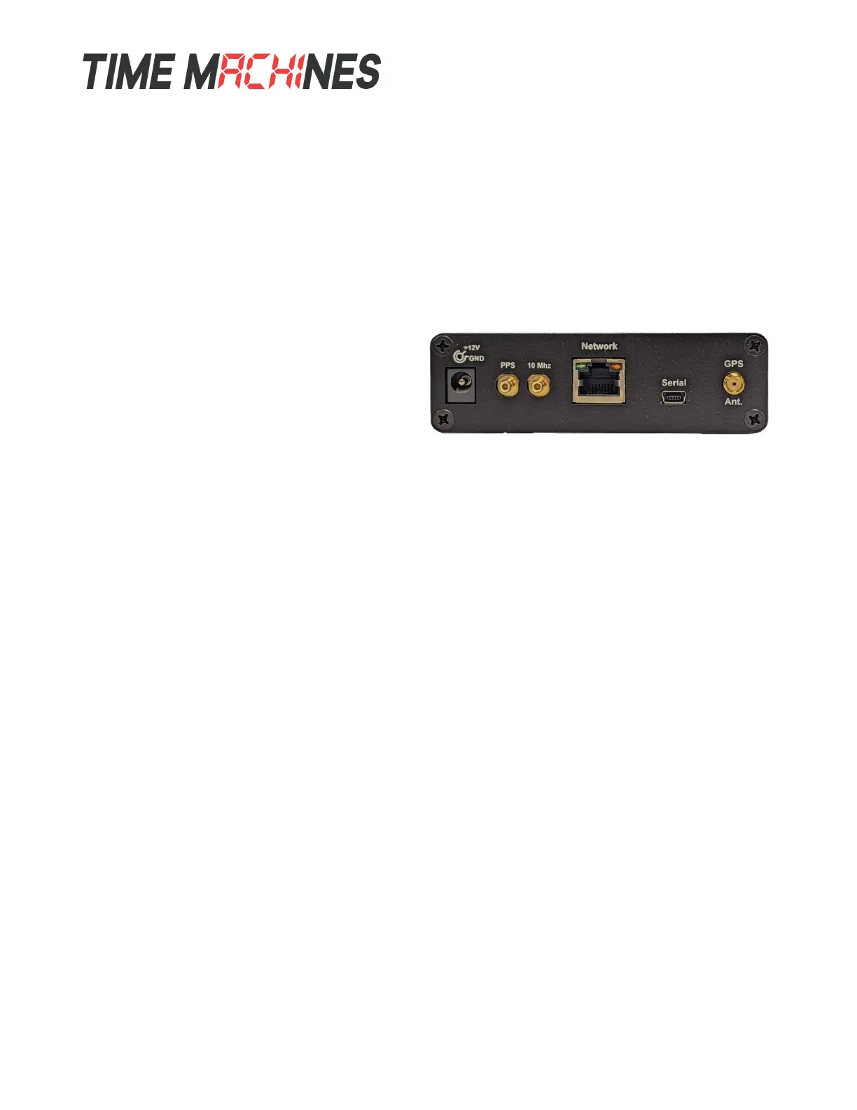
2.2 Connections
2.2.1 Antenna
The GPS antenna is connected through the
circular female SMA connector on the rear of the
Time Server. By default, the GPS antenna
connection provides 5.0V to power the LNA in
the GPS antenna. This is correct for the supplied GPS patch antenna with the magnetic base. This
voltage can be changed with a jumper on the inside of the Time Server. The Time Server has to be
opened up and a jumper moved.
Jumper J8
A: 3.3V B: 5.0V (default)
The only time this jumper would changed would be to allow use of a different antenna that requires
+3.3V max for the LNA in the antenna.
2.2.2 Power
A +12V power supply is supplied with the unit. Connect to your local power outlet and the barrel
connector to the rear of the Time Server. The time server will begin trying to find the GPS satellites.
On power-up, synchronization to the GPS satellites will take several minutes. No battery backup of
position is provided to allow for a warm start so the Time Server is always starting from scratch in
determining its location to achieve GPS lock.
2.2.3 Network
Connect the 10/100 RJ45 port on the back of the Time Server to a network connection. Verify that the
network settings are correct for your system. See the configuration section of this manual for more
information on doing this.
2.2.4 Serial
The serial port is connected by a USB-Mini type connector and will enumerate as a COM port on most
modern operating systems. It is an output only port use for some basic status information. No
configuration of operating system access is possible through this port. It is setup as 115200,n81.
2.2.5 PPS (2500C Only)
The PPS output is a 3.3V TTL output driven by the DPLL hardware and derived from the 1PPS output
Installation and Operations Manual | Page 2
Web / timemachinescorp.com Email / tmsales@timemachinescorp.com Phone / (402) 486-0511