of the GPS receiver. It is a 50% duty cycle output where the positive rising edge denotes the second
boundary. The GPS receiver 1PPS output is specified at +/10 nano-seconds. Best results are achieved
with an outdoor antenna with a full 360 degree view of the sky. Degraded signal quality will degrade
the precision of this output.
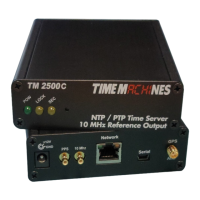
2.2.6 10MHz (2500C Only)
The 10MHz output is a 3.3V TTL signal driving by the DPLL hardware and derived from the frequency
corrected internal OCXO. It is synchronized to the 1PPS such that it will have a postive rising edge
that corresponds to the rising edge of the 1PPS signal.
2.2.7 Front Panel Indications
The front panel of the Time Server is very basic in its appearance. Three LEDs show the current status
of the unit. The “POW” LED indicates that the unit is receiving power through its wall power supply.
To serve time, an accurate GPS lock is required beyond just location information. The GPS lock
process proceeds through several steps and can be followed by watching the two front Yellow LEDs,
LOCK and SEC. Initally, when no lock is present, the Yellow LEDs will be OFF. When a 2D lock is
achieved, the LOCK LED will begin to BLINK. This is the first stage of GPS lock process. When the
LOCK LED goes to a solid ON state, the GPS now has a 3D lock. The last stage of the GPS lock is the
timing lock. This signifies that the GPS has the most accurate time base available for use in serving
time. To achieve the greatest PTP accuracy, this is required. Once the timing lock has occurred, the
SEC LED will begin to blink once per second.
It is also possible for the LOCK LED to turn off, or blink, after a GPS timing lock has occurred and the
SEC LED continues to blink. This signifies that the TM2X00 has an accurate internal time and is
serving time, but is trying to re-establish the timing lock because it was lost for some reason.
3 Configuration
3.1 Web Page – Default username/password is “admin/tmachine”
3.2 Default IP address is 192.168.1.20
All Time Server parameters are accessed on the configuration web page. The page can be accessed by
pointing any web browser at the IP address of the Time Server. The initial IP address is 192.168.1.20
from the factory.
Installation and Operations Manual | Page 3
Web / timemachinescorp.com Email / tmsales@timemachinescorp.com Phone / (402) 486-0511