DSP-599zx Audio Noise Reduction Filter
March 6, 1997 6-1
6
Data Mode
Introduction
Data signals like CW and RTTY require bandpass filters with steep skirts
and linear phase response. Linear phase response maximizes the usable sig-
naling rate for a given bandwidth. The baud rate, center frequency and fre-
quency shift of a data signal determine the bandwidth of filter for that data
signal. In the Data Filter mode, the DSP-599zx has an array of band-pass fil-
ters optimized for the most common high frequency (1.8-30 MHz) data
modes.
The DSP-599zx also has a built in RTTY modem. The RTTY modem de-
modulates received RTTY audio tones and generates audio frequency shift
keyed signals.
A third option within Data mode is the RTTY remodulator mode. This is a
special receiving mode that regenerates the data tones to send them to an ex-
ternal modem.
Configuration of the RTTY modem is done as part of Setup - Data. You can
choose to have channel A line output function as a the RTTY modem output
or have channel B function as the RTTY modem output.
The RTTY remodulator is selected by pressing the
[Function]
key.
Operations Common To All Data Types
Basic Data Mode Operation
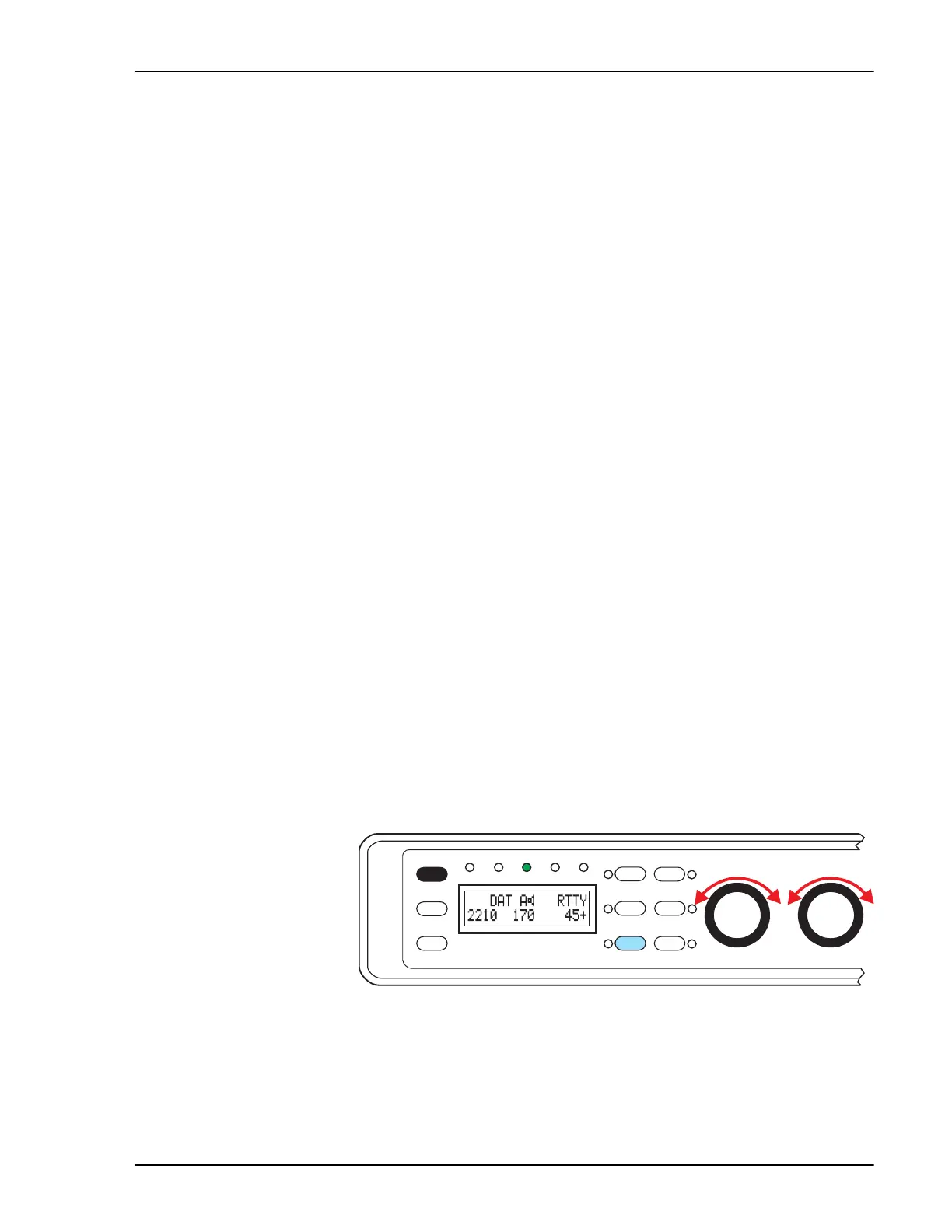
• Pressing
[Mode]
to select the Data mode.
• Turn the left knob to select the appropriate data filters.
• Turn the middle knob slightly to vary the filter bandwidth to suit the
band conditions.
Function
6
Shift
5
AGC
3
Bypass
Data
DSP-599zx
CW
Voice
Mode
1
Random
4
Tone
2
599-056
Setup
Test
Rcl/Store
Spkr/Chan
High Pass
Center Freq
Timewave
Low Pass
Bandwidth
March 6, 1997


 To Next Page