Version D January 2021
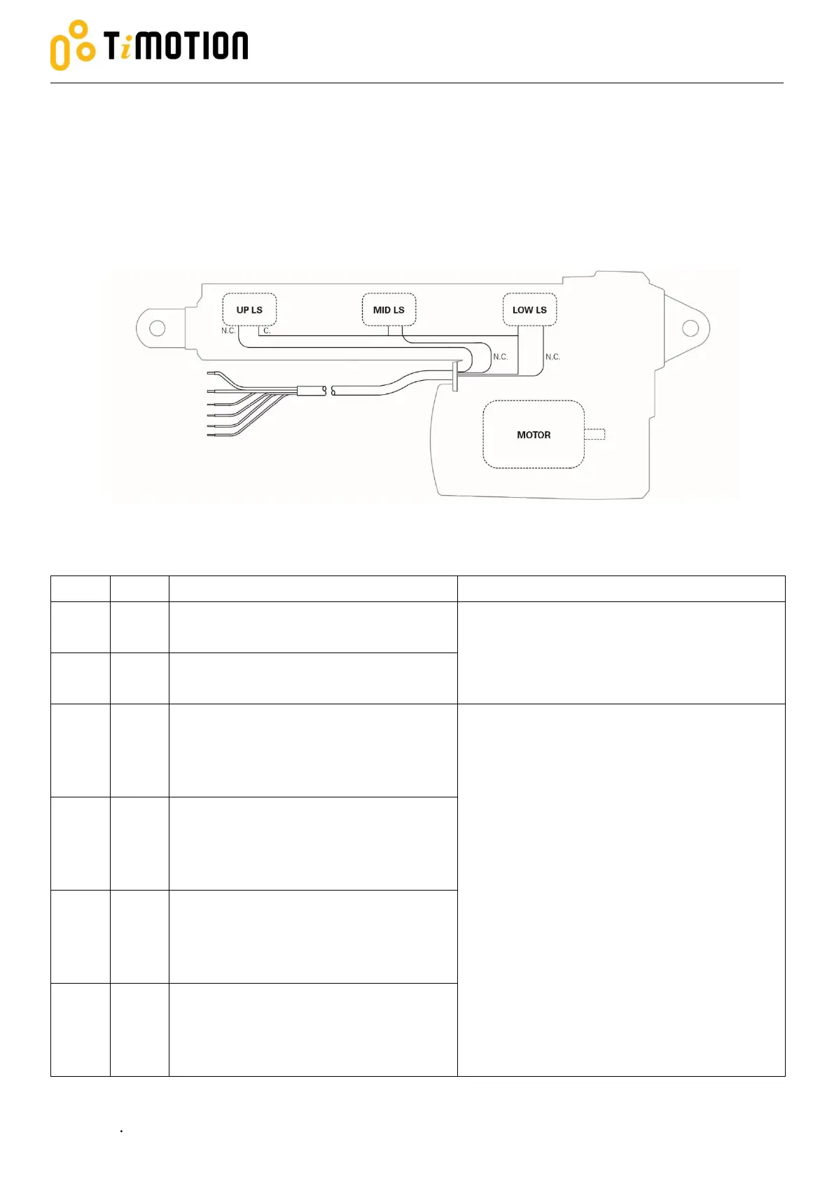
2.3.4 Two limit switches send the signal, and an additional limit switch sends
a signal at specific stroke positions
The actuator is equipped with two limit switches at the end of the strokes. When the actuator moves to the
end of each stroke, each limit switch sends out the end of stroke voltage signal, and an additional limit switch
sends out the signal at specific stroke positions.
*Please refer to section 2.3.2 for cut current module.
Connect to Vm+ to extend the actuator.
Connect to Vm- to retract the actuator.
24V version: Input voltage 18~32 V DC.
12V version: Input voltage 9~16 V DC.
Connect to Vm- to extend the actuator.
Connect to Vm+ to retract the actuator.
Connect to common pin (C.)
The signal, NOT potential free, actively outputs
voltage at the end of each stroke and when
the actuator moves to the position where the
additional limit switch is triggered.
Both the white and blue signal wires are a
normal closed circuit when the actuator is
between the end of each stroke.
The additional limit switch, installed in position
by customer request, is factory preset and
non-adjustable
Connect the additional limit switch signal with
max 32V, <1A.
Connect to up limit switch normal
closed pin (N.C.)
Connect to low limit switch normal
closed pin (N.C.)
Connect to middle limit switch normal
closed pin (N.C.)
Yellow
Green
Red
White
Blue
Black