Version D January 2021
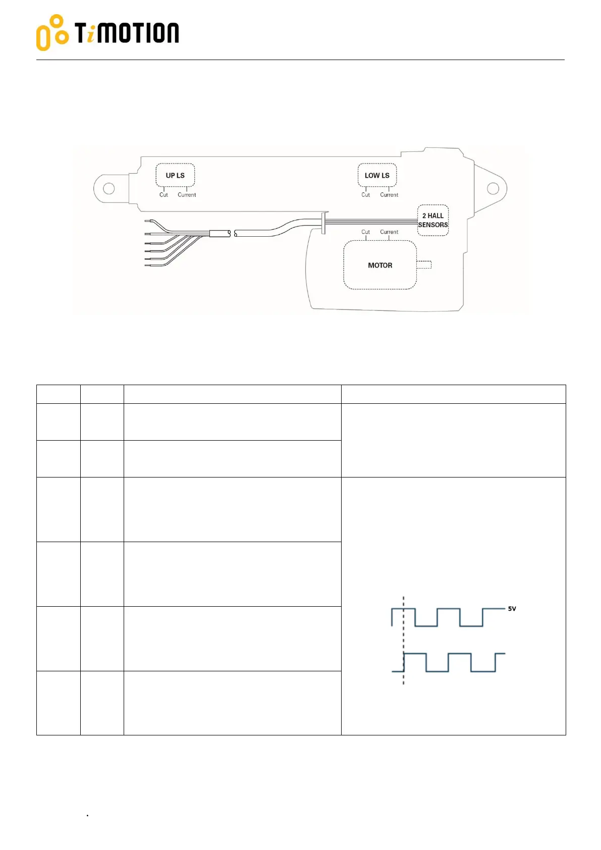
2.3.7 Two limit switches and double Hall sensors
The actuator is equipped with two limit switches to cut the current of the motor when the actuator moves to
the end of each stroke, and with double Hall sensors sending position signal output.
*Please refer to section 2.3.2 for cut current module.
Connect to Vm+ to extend the actuator
Connect to Vm- to retract the actuator
24V version: Input voltage 18~32 V DC
12V version: Input voltage 9~16 V DC
Connect to Vm- to extend the actuator
Connect to Vm+ to retract the actuator
+5V DC input signal power for Hall sensor
board.
Hall sensor output signal type is square
wave with Hi voltage 5V and Low voltage
0V, and with the output current of 0.1A
(please refer to the approval drawing for the
resolution and details).
S1 leads 90 degrees’ phase to S2.
Hall sensor circuit is independent to motor
power circuit.
Output Hall sensor signal S1 during the
actuator moves.
Output Hall sensor signal S2 during the
actuator moves.
Hall sensor signal ground.
Yellow
Green
Red
White
Blue
Black