Version D January 2021
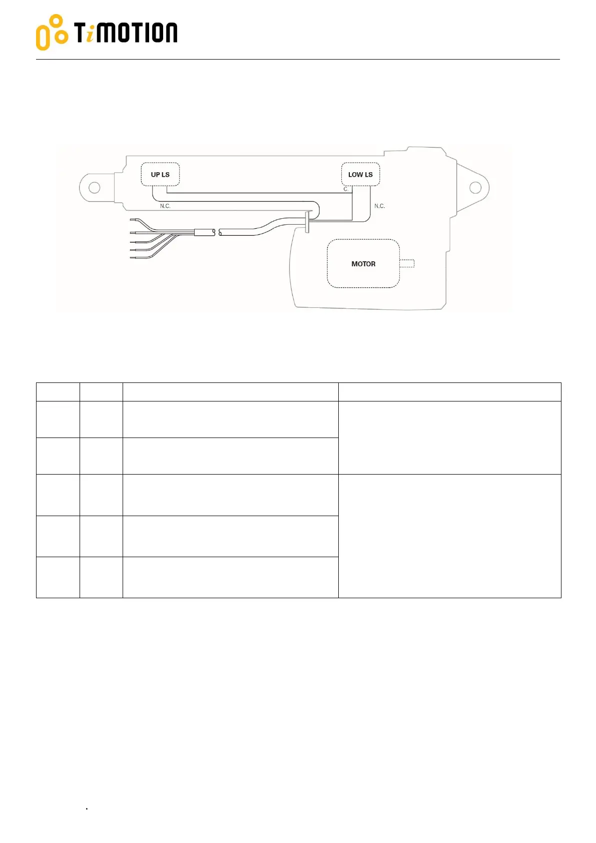
2.3.5 Two limit switches send the signal output
The actuator is equipped with two limit switches. When the actuator moves to the end of each stroke, each
limit switch sends out the end of stroke voltage signal at the same time.
Connect to Vm+ to extend the actuator
Connect to Vm- to retract the actuator
24V version: Input voltage 18~32 V DC
12V version: Input voltage 9~16 V DC
Connect to Vm- to extend the actuator
Connect to Vm+ to retract the actuator
Connect to common pin (C.)
The signal is potential free and independent
from the motor power circuit.
The signal is short circuit when the actuator
moves to each end of stroke.
Connect the limit switches signal with max
32V, <1A.
Connect to up limit switch normal closed
pin (N.C.)
Connect to low limit switch normal closed
pin (N.C.)
Yellow
Green
Red
White
Blue