5
IOM - FFDE
Redefine your comfort zone. ™ | www.titus-hvac.com
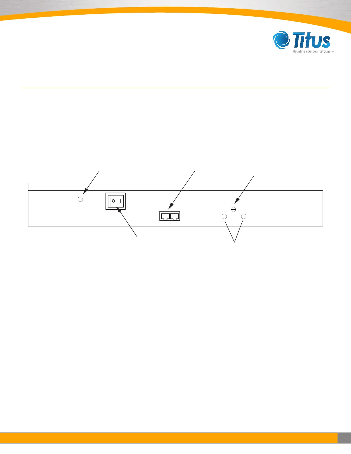
CAT 5e
Network Cable Connection
(RJ45 Connector)
ON/OFF Switch
RPM Test Probe Jack Comm.
Filter Indicator Light
Pressure Switch Adjuster
Manual Speed Potentiometer
Unit Control Box
ON/OFF SWITCH - SPEED/AIRFLOW ADJUSTMENT
All units are equipped with a two-position rocker switch (ON/OFF), which is located on the side of the electrical box, on top of
the unit. Unless specified otherwise units are furnished with a Universal Control Card to enable adjustment of airflow or set to
your means of communication. (see Page 6 for CON4 Universal Card Card Set Up).
Note: The CAT5e/RJ45 network ports are non-directional (i.e. in or out). Be sure to examine your cabling to insure that there is no cross-over wired cables.
FILTER INDICATOR LIGHT OPTION:
The pressure switch for the filter indicator light option is set at 0.60 in wc
from the factory. The set point for the pressure switch can be adjusted
between 0.50 in wc and 3.00 in wc by turning the set screw, accessible for
the front of the control enclosure. Counterclockwise rotation will increase
the set point differential for switching; clockwise rotation will reduce the
set point.
The process to adjust this for a specific application is detailed below:
Step 1. Adjust fan speed to highest setting
Step 2. Measure and note initial pressure differential between ceiling
plenum and unit plenum (downstream of the fan & upstream of the filter)
Step 3. Restrict discharge airflow incrementally to increase differential
pressure until measured value matches filter loading requirements for
the project
a. If no specific filter loading requirements are specified a general
recommendation is to use twice the pressure differential
measured in step 2
Step 4. With the unit discharge blocked, adjust the set point of the
pressure switch
a. If the indicator light is illuminated, increase the set point of the
pressure switch (CCW rotation) until the is unilluminated
i. Slowly decrease set point until light illuminates
b. If the indicator light is unilluminated, slowly decrease the set point
of the pressure switch (CW rotation) until the light illuminates
Step 5. Remove obstruction(s) from the unit discharge
Step 6. Adjust fan speed to operational set point