Follow the instructions below, both to prevent accidents when making repairs and to ensure post-repair
product safety.
Do not apply voltages other than those specified for the equipment or its compo-
nents.
Applying voltages other than the rated voltage could cause electrical breakdown or over-current, possi-
bly resulting in electric shock or fire. Power is supplied from the VM-3000 System.
After replacing parts, be sure to return the new parts and any other affected parts
to their previous configuration.
Check that all screws, parts, and wiring removed or changed during servicing have been restored to
their original states. Also, confirm that no damage has occurred around the serviced area.
Do not modify the design of circuit boards or other electronic elements.
Modifying circuit boards could cause electric shock or result in a fire hazard due to excessive heat
build-up. User modification automatically exempts the manufacturer from all personal and property lia-
bility caused by such modification, and the user who carried out such modification shall be solely
responsible for such accidents.
Since lead can become an environmental contaminant, this unit has been manufactured using solders
that contain no lead in the printed circuit board.
[While conventional solders are alloys of zinc and lead, lead-free solder is comprisend of an alterna-
tive alloy that contains no lead.]
NOTES
• Circuit boards using lead-free solder bear a lead-free solder designation. To maintain the integrity
of this designation, be sure to use lead-free solder when repairing such lead-free solder circuit
boards. Boards not marked with the lead-free solder designation may legally be serviced using
conventional solders.
• Because the melting point of lead-free solder (approximately 220°C) is 30°C-40°C higher than that
of conventional (lead-zinc alloy) solder, it tasks little longer to melt. It is recommended that a sol-
dering iron with controllable temperature be used and set to 20°C higher than would normally be
used with conventional solder.
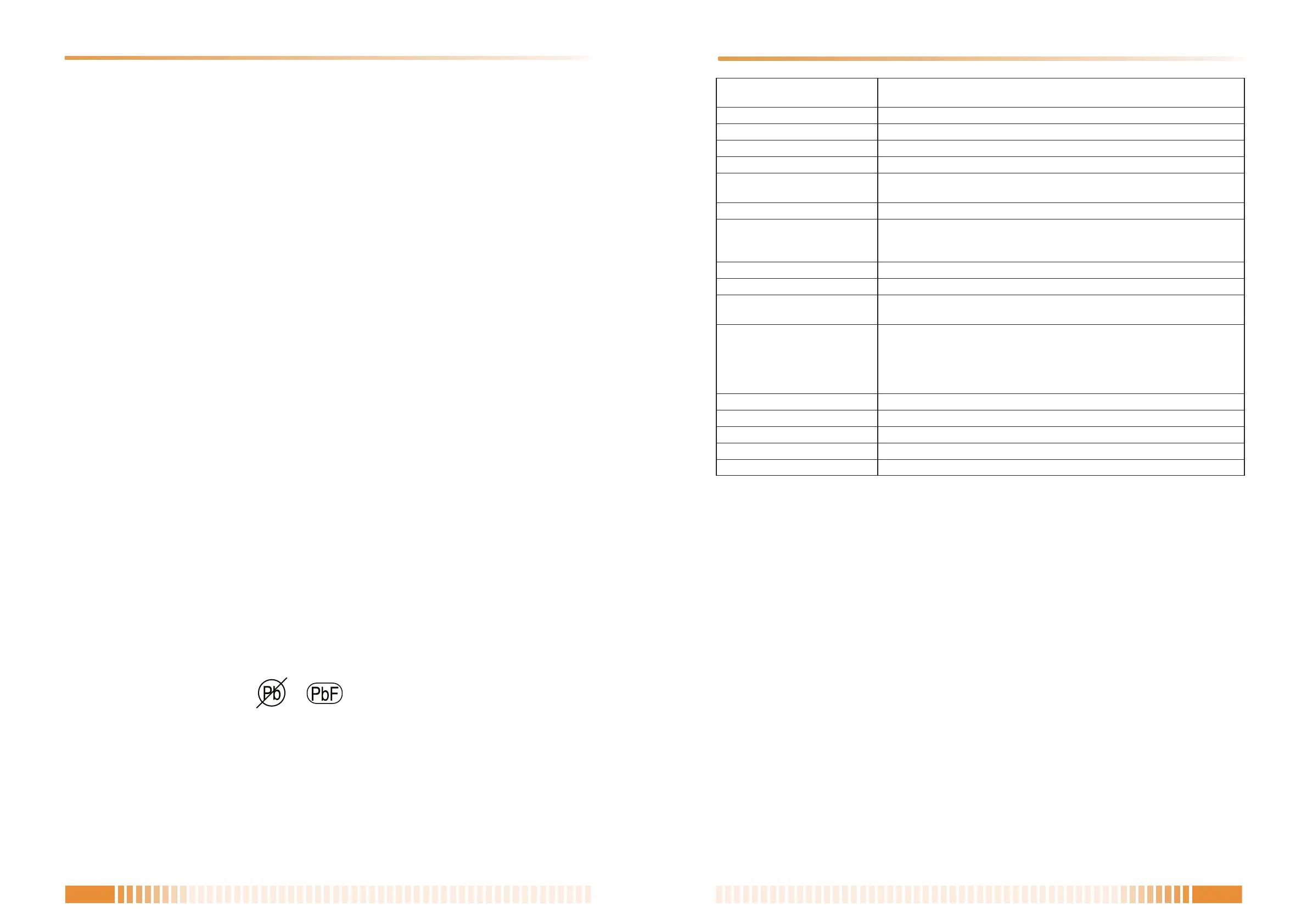
Identifying printed circuit boards that use free-lead solder
Printed circuit boards that use lead-free solder have the following designation printed or stamped on
either side of the board.
• About lead-free solders
24 V DC
(operating range: 15 – 40 V DC, supplied from the VM-3000 system)
120 mA (RM-300MF), 660 mA (with 3 RM-320Fs connected)
200 – 15kHz
1% or less
55 dB or more
Unidirectional dynamic microphone with talk key, compressor (on/off
switchable)
Microphone volume control, buzzer volume control
Main line: Shielded CPEV cable (each one pair of Audio line, Data line,
Power supply line) or Category 5 Shielded Twisted-Pair straight cable
for LAN (CAT5-STP), M3 screw terminal
Total 800 m
Max. 3 units
Emergency key, Evacuate key, Alert key, Emergency reset key,
CPU switch, Reset key
Power Indicator, Emergency Indicator, Communication Failure Indicator,
CPU OFF Indicator, Evacuation Announcement Indicator,
Alert Announcement Indicator, Emergency Reset Indicator,
Microphone In-Use Indicator, Emergency Broadcast Equipment In-Use
Indicator
–5°C to +45°C
5% to 95% RH (no condensation)
ABS resin, blueish gray (PANTONE 538 or its equivalent)
200 (w) x 215 (h) x 82.5 (d) mm
1.1 kg
Power Source
Current Consumption
Frequency Response
Distortion
S/N Ratio
Microphone
Volume Control
Connection Cable and Terminal
Maximum Cable Distance
No. of Connectable RM-320Fs
Operation
Indicator
Operating Temperature
Operating Humidity
Finish
Dimensions
Weight
Wall mounting bracket unit ................................... 1
Wall mounting screw ............................................ 2
Note: The design and specifications are subject to change without notice for improvement.
• Accessories