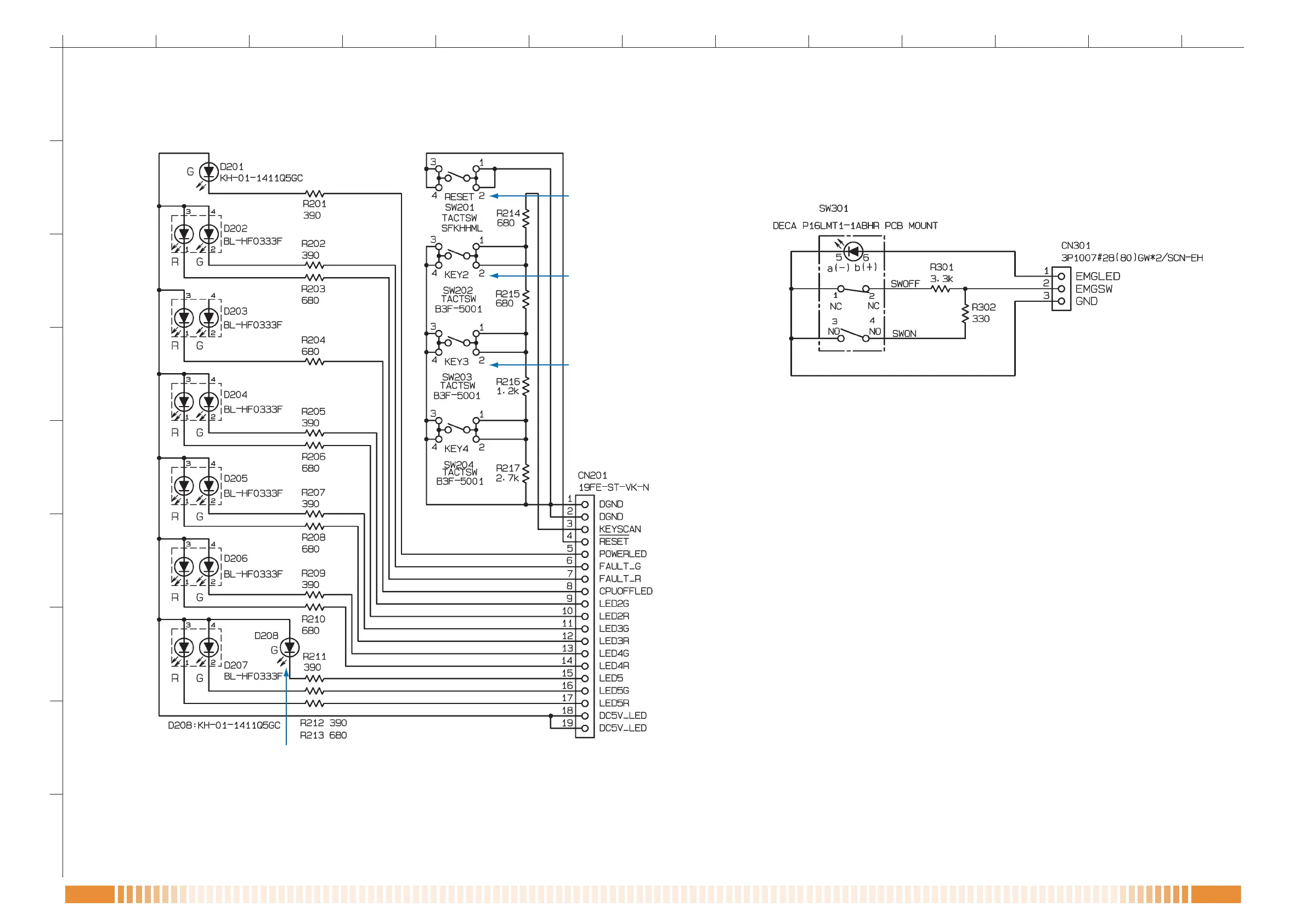
EasyManua.ls Logo

Toa RM-300MF - Sw Pcb; Emg Sw Pcb

Toa RM-300MF
12 pages
Print Icon
To Next Page IconTo Next Page
To Previous Page IconTo Previous Page
Loading...
SCHEMATIC DIAGRAMS
1
A
B
C
D
E
F
G
H
23 654 789 11121310
I
8 8
RM-300MF
To CPU PCB
CN3
Power Indicator
Communication
Failure Indicator
CPU OFF Indicator
Evacuation
Announcement
Indicator
Alert Announcement
Indicator
Emergency Reset
In-Progress Indicator
External Emergency
Equipment In-Use
Indicator
Emergency Microphone
In-Use Indicator
Emergency Reset Key
Alert Announcement
Start Key / Lamp Test Key
Evacuation
Announcement
Start Key
RM Reset Key
• SW PCB
To CPU PCB
CN2
Emergency
Activation Switch
• EMG SW PCB
RESISTANCE VALUES IN OHMS. INDUCTANCE VALUES IN HENLY.
ALL RESISTORS 1/16W UNLESS OTHERWISE DESIGNATED.
CAPACITANCE VALUES IN FARADS, 50V UNLESS OTHERWISE DESIGNATED.
CIRCUITS ARE SUBJECT TO CHANGE WITHOUT NOTICE FOR FURTHER IMPROVEMENT.
RESISTANCE VALUES IN OHMS. INDUCTANCE VALUES IN HENLY.
ALL RESISTORS 1/16W UNLESS OTHERWISE DESIGNATED.
CAPACITANCE VALUES IN FARADS, 50V UNLESS OTHERWISE DESIGNATED.
CIRCUITS ARE SUBJECT TO CHANGE WITHOUT NOTICE FOR FURTHER IMPROVEMENT.

Related product manuals