GENERAL PURPOSE BROADCAST VOICE ANNOUNCEMENT BOARD
4-3-2
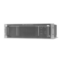
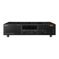
VM Amplifier
EV-200
13 1
25 14
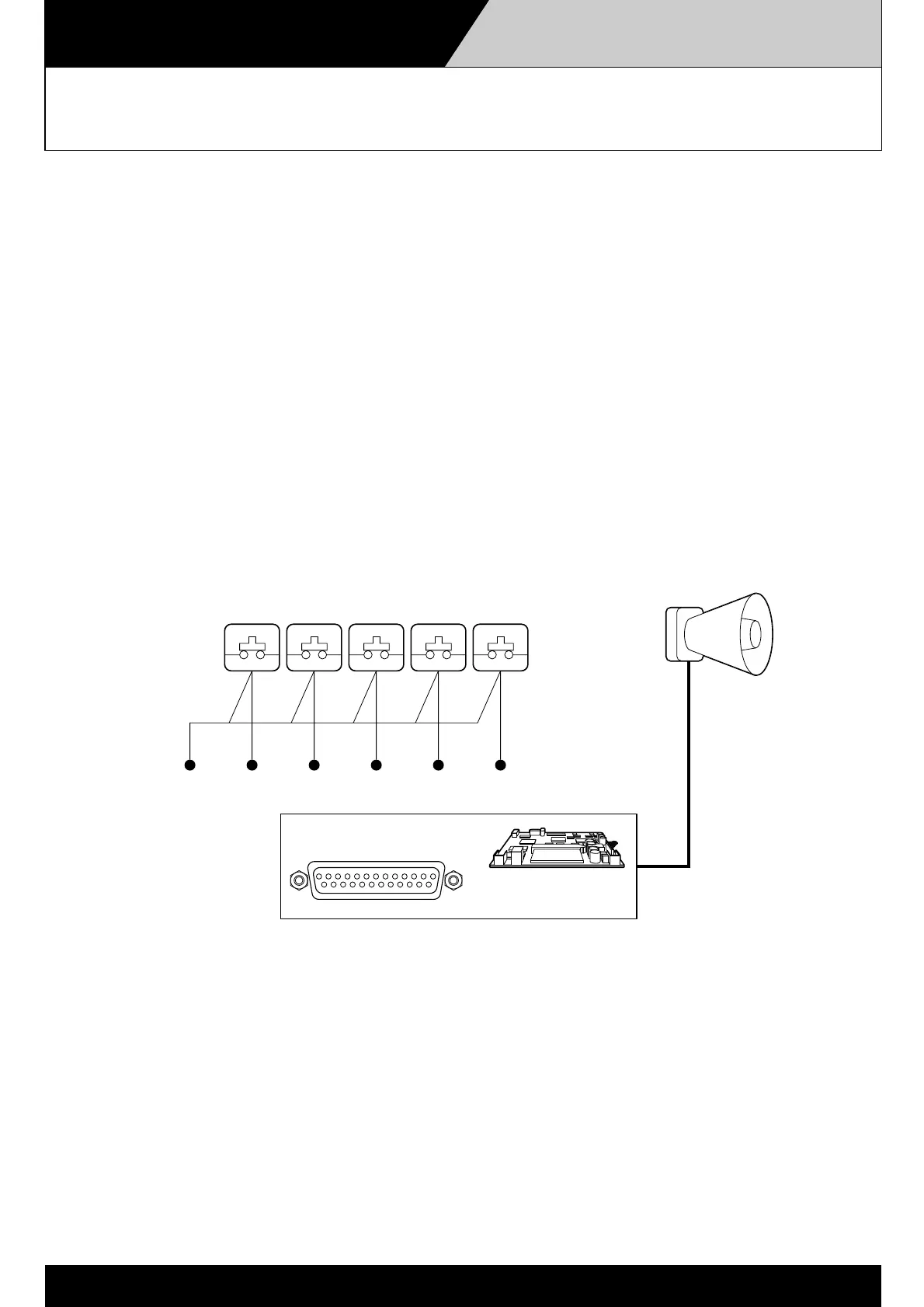
CONTROL I/O
No-voltage make contact
(one shot signal)
pin no.
3
pin no.
4
pin no.
5
pin no.
6
pin no.
7
pin no.
16 – 20 (GND)
Message Activation
Messages recorded on the CompactFlash memory card can be played back by activating (no-voltage
"make" contact) the control I/O terminal located on the VM amplifier's rear panel, as in the case of the
Remote Microphone.
Record five different general-purpose messages on the CF card. If the pin corresponding to each message
is activated, the messages can be individually played back.
MESSAGE 1 ACTIVATION: Pin No. 3
MESSAGE 2 ACTIVATION: Pin No. 4
MESSAGE 3 ACTIVATION: Pin No. 5
MESSAGE 4 ACTIVATION: Pin No. 6
MESSAGE 5 ACTIVATION: Pin No. 7
Ground: Pin Nos. 16 -20
NOTE: Custom-made switches that are appropriate for installation conditions are required to activate the messages.
(Please refer to P. 4-2-1, Operation and Broadcasting from the Remote Microphone.)
NOTE: A message activated by switches cannot be stopped till its end, while the message activated by a Zone/Message selector key on
remote microphone can be stopped during the broadcast by pressing the key again.
 Loading...