EasyManua.ls Logo

Toa VM-3360VA User Manual

Toa VM-3360VA
16 pages
To Next Page IconTo Next Page
Page #1 background imageLoading...
Page #1 background image
INSTALLATION GUIDE FOR
VM-3000 SERIES
INTEGRATED VOICE EVACUATION SYSTEM
For Service Technicians only
This manual describes works to be performed with the unit's case open.
Leave all these works to a qualified electrician.
Do not pass this manual to users.
Be sure to switch off the system power before starting any work described herein.
Doing otherwise may cause electric shocks.
For switching off the system power, refer to p. 2 in this manual.
WARNING
TABLE OF CONTENTS
1. SWITCHING OFF THE SYSTEM POWER ................................................. 2
2. INPUT TRANSFORMER INSTALLATION AND
MIC INPUT SENSITIVITY CHANGE
............................................................. 3
3. VP-200VX INSTALLATION IN THE VP-2241/2421AND
GROUND LIFT SETTING
3.1. Installing the VP-200VX in the VP-2241/2421 ................................................... 5
3.2. Ground Lifting Using the VP-200VX ................................................................... 6
4. SPEAKER LINE VOLTAGE CHANGE
4.1. VM-3240VA/3360VA and VM-3240E/3360E ...................................................... 7
4.2. VP-2241 and VP-2421 ....................................................................................... 8
5. DC FUSE REPLACEMENT
5.1. VM-3240VA/3360VA and VM-3240E/3360E ...................................................... 9
5.2. VX-2000DS ........................................................................................................ 9
5.3. VP-2241 and VP-2421 ..................................................................................... 10
6. CONNECTING TO THE SX-2000 SYSTEM
6.1. General Description ......................................................................................... 11
6.2. VP-200VX Installation in the VM-3240VA/3360VA .......................................... 12
6.3. Example of Connections between the SX-2100AO, VM-3240VA/3360VA,
and VP-2241/2421 ........................................................................................... 13
6.4. Operating the Combined System of the VM-3240VA/3360VA and
the SX-2000 System ........................................................................................ 14
6.5. Example When the VM-3240VA/3360VA Connected to
the SX-2000 System Fails ................................................................................ 15
Question and Answer IconNeed help?

Do you have a question about the Toa VM-3360VA and is the answer not in the manual?
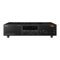
Toa VM-3360VA Specifications

General IconGeneral
Output Power360 W
Frequency Response50 Hz - 20 kHz
Dimensions420 x 107.6 x 367.7 mm
Power SourceAC 220-230 V, 50/60 Hz
InputsMIC: -60 dB
OutputsSpeakers: 4Ω, 70V, 100V
Input Impedance10 kΩ

Summary

System Power Off Warning

Switching Off System Power

Input Transformer and Mic Sensitivity

Transformer-Balanced Input Conversion

Procedure to convert electronically balanced inputs to transformer-balanced using jumpers.

Microphone Input Sensitivity Adjustment

Steps to adjust microphone input sensitivity by cutting specific jumper wires.

VP-200VX Installation and Ground Lift

VP-200VX Installation in VP-2241/2421

Detailed steps for installing the VP-200VX module into the VP-2241/2421 amplifier.

Ground Lifting Using VP-200VX

Instructions on how to use the VP-200VX's Ground Lift jumper to cut ground loops and reduce hum.

Speaker Line Voltage Adjustment

VM-3240/3360 Series Voltage Change

Procedure to change speaker line voltage from 100V to 50V or 70V on VM-3240/3360 series.

VP-2241/2421 Voltage Change

How to change the speaker line voltage for VP-2241 and VP-2421 amplifiers to 50V or 70V.

DC Fuse Replacement

VM-3240/3360 Series Fuse Replacement

Instructions for replacing blown DC fuses in VM-3240/3360 series amplifiers.

VX-2000DS Fuse Replacement

Procedure for replacing blown DC fuses in the VX-2000DS unit.

VP-2241/2421 Fuse Replacement

Steps to replace the blown DC fuse in VP-2241 and VP-2421 amplifiers.

Connecting to SX-2000 System

SX-2000 System Integration Overview

Overview of integrating VM-3240VAs/3360VAs with the SX-2000 system for expanded capacity.

VP-200VX Installation in VM-3240/3360VA

Procedure to install the VP-200VX module into the VM-3240VA/3360VA unit.

Example Connections: SX-2100AO, VM-3240/3360VA, VP-2241/2421

Diagram illustrating example connections between SX-2100AO, VM-3240/3360VA, and VP-2241/2421.

Operating Combined VM-3240/3360VA and SX-2000 System

How to operate the combined system, including software settings for control input.

VM-3240/3360VA Failure Example in SX-2000 System

Scenario illustrating system operation when the VM-3240/3360VA fails and standby is activated.

Related product manuals