6
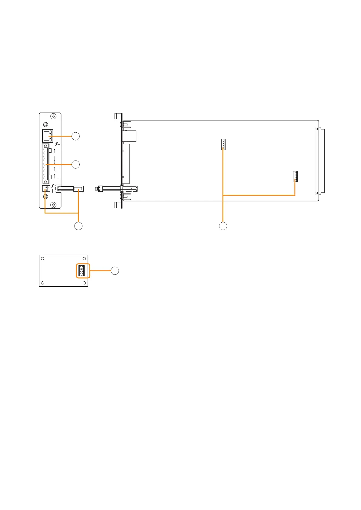
4.1. Pilot Tone Detection Module VX-200SP-2
STANDBY
PA BUS
VX-200SP-2
PA
LINK
H
LINE
MONITOR
C H
SP
OUT
C H
PA
IN
CN1 N2C
ATT
CTRL
H
C
E
[Side][Front]
End-of-line (EOL) unit
1
4
3
2
5
1.Poweramplierlinkconnector[PALINK]
This RJ45 connector connects to the PA LINK
connectoroftheVP-200VXPowerAmplierInput
moduleortheVP-3000seriesPowerAmplier.
Both LEDs on this connector are not used.
2. VX-200SP plug-in screw connector
Signallinestobeconnectedareshownbelow:
•Linemonitorinput[LINEMONITOR]
Monitors connected speaker lines.
ConnectbywiringfromtheSPOUT.
•Externalattenuatorcontrol[ATTCTRL]
Permits connection of a 3- or 4-wire system
attenuator.
For the attenuator connection, refer to p. 16.
•Speakeroutput[SPOUT]
Connects to the speaker.
•Poweramplifierinput[PAIN]
Connects to the power amplifier's speaker
output terminal.
3.Standbyamplierbusconnector
[STANDBY PA BUS]
Connects to all outputs of a single VX-2000SF unit
to be switched over to the standby amplifier when
the power amplifier fails.
For details, refer to the VX-2000 series Instruction
manual.
4. VX-200SE mounting connector
UsedtomounttheVX-200SEEqualiserCard.
5. Speaker line connection terminal
Connect the EOL unit to the end of the speaker
line.
Be sure to connect the speaker's shield cable to
the E terminal of EOL unit, and the other end of the
cable to the equipment's functional ground of the
VX-2000 system.
Install this module in the VX-2000SF Surveillance Frame to detect speaker line short circuits, open circuits by
monitoring the terminated resistance value of the EOL unit, and ground fault.
The pilot tone can be detected by using the supplied EOL unit in combination.
Please equate this module as the VX-200SP when setting it on the PC software.
4. NOMENCLATURE AND FUNCTIONS