7
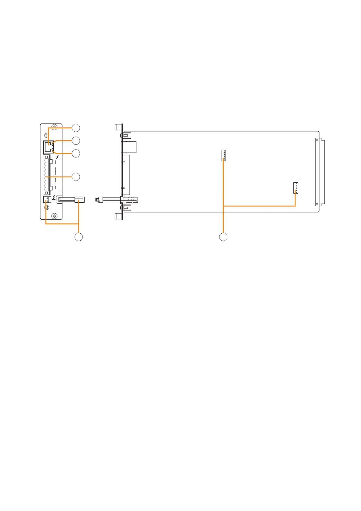
4.2. Impedance Detection Module VX-200SZ-2
STANDBY
PA BUS
PA
LINK
A
B
H
SP
OUT
CH
SP
OUT
AB
C H
PA
IN
CN1 N2C
ATT
CTRL
VX-200SZ-2
[Side][Front]
3
4
5
6
1
2
1.Poweramplierlinkconnector[PALINK]
This RJ45 connector connects to the PALINK
connectoroftheVP-200VXPowerAmplierInput
moduleortheVP-3000seriesPowerAmplier.
2. Speaker line A status indicator [A]
Shows the status of speaker line connected to the
SPOUTAterminal.
For details, refer to p. 8.
3. Speaker line B status indicator [B]
Shows the status of speaker line connected to the
SPOUTBterminal.
For details, refer to p. 8.
4. VX-200SZ plug-in screw connector
Signallinestobeconnectedareshownbelow:
•Externalattenuatorcontrol[ATTCTRL]
Permits connection of 4-wire system attenuators.
For the connection instructions, refer to p. 15.
The attenuator bypass method can be changed
from relay to photocoupler type. For the
modification instructions, refer to p. 11.
•
Speaker outputs A and
B
[
SP OUT A, SP OUT B
]
Connect the speakers.
•Poweramplifierinput[PAIN]
Connects to the power amplifier's speaker
output.
5.Standbyamplierbusconnector
[STANDBY PA BUS]
Connects to all outputs of a single VX-2000SF unit
tobeswitchedovertothestandbyamplierwhen
thepoweramplierfails.
For details, refer to the VX-2000 series Instruction
manual.
6. VX-200SE mounting connector
UsedtomounttheVX-200SEEqualisercard.
Install this module in the VX-2000SF Surveillance Frame to detect speaker line short circuits, open circuits by
comparing impedance readings, and ground fault.
Please equate this module with the VX-200SZ when setting it on the PC software.
Important Note
WhencombiningthismodulewiththeVP-200VXBGMInputModule,thenthesignallevelappliedtotheVP-
200VX's external input should be low, i.e. about 10 dB below the rated level. The level can also be reduced by
the volume adjustment.