6
[Fault indication]
If any of the following indicators on the front panel remains unlit, the unit is judged failed. In such cases, remove
the cause of the failure, and restore the unit to normal operation.
Note
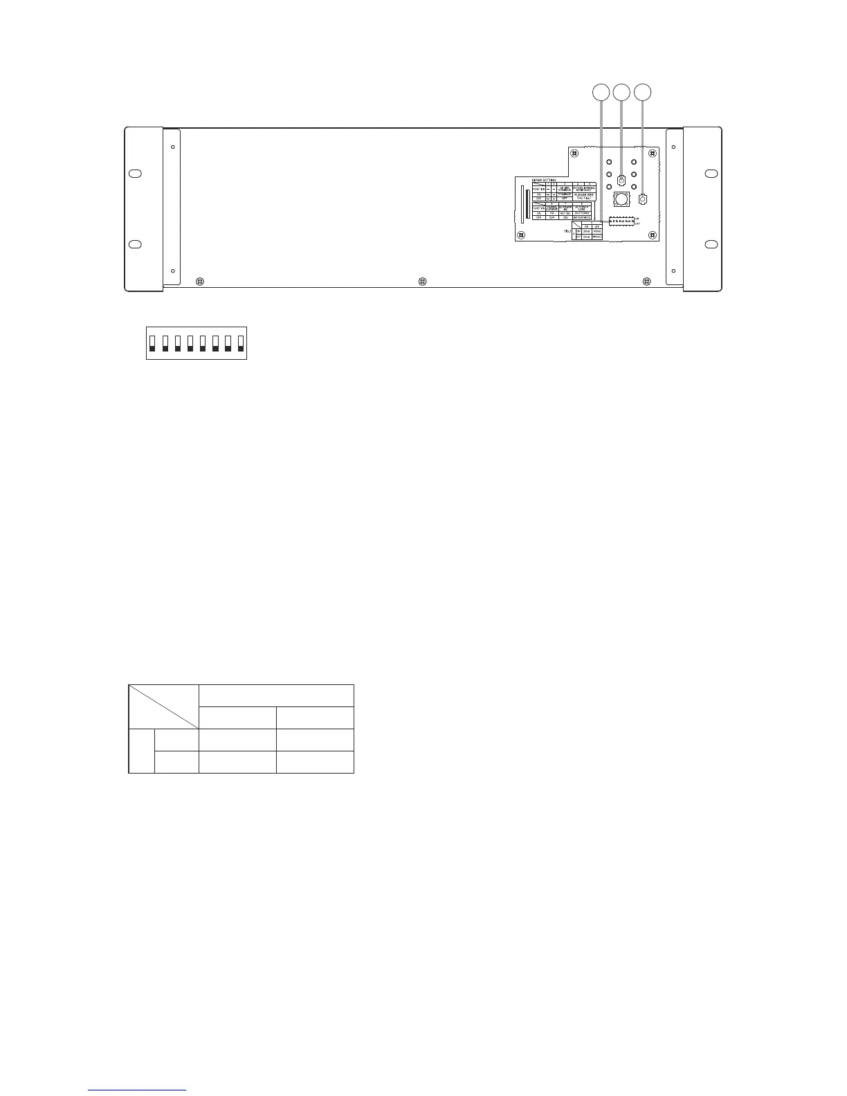
[Front (with the front panel removed)]
9
7
8
7. DIP switch
8 1
ON
OFF
Be sure to leave both switches OFF.
Switches 3 and 5: ON
Each switch function is described as follows.
Switch 3
Set to ON when no other VX-3000DS unit is
connected or when this unit is the last one of
connected units.
Switches 4 and 5
Set the upper limit value of the internal battery
resistance and battery connection cable resistance
to be monitored for fault detection.
Setting switch combination of 4 and 5 is as follows.
5
ON OFF
4
ON
1
OFF DISABLE
1
Settings compliant with EN 54-4.
Switch 6
Sets the battery charging current.
ON: 11 A (100 to 200 Ah)
2
: 5.5 A (under 100 Ah)
2
Settings compliant with EN 54-4.
Switch 7
Sets whether the failure detection function is used
for the AC Power IN2.
ON: Failure detection function disabled.
3
: Failure detection function enabled.
3
Settings compliant with EN 54-4.
Set to ON when using the AC Power IN1 only, and
set to OFF when using both AC Power IN1 and IN2.
Note
The AC inlet IN2 works irrespective of Switch 7
setting as long as power is applied to it. Therefore,
be sure to set Switch 7 to OFF (enabling the failure
detection function) whenever IN2 is used.
Switch 8
Places the unit in AC operation mode or battery
mode.
ON: All power outputs are shut down when AC
power fails even if backup batteries are
connected. (AC operation mode).
OFF: Battery is used as backup power supply
when AC power fails. (Battery mode)
Be sure to set to OFF in normal operation.
8. Shutdown button
Pressing this button forcibly shuts down this unit
switch (7).
9. Reset button
Pressing this button resets this unit.