15
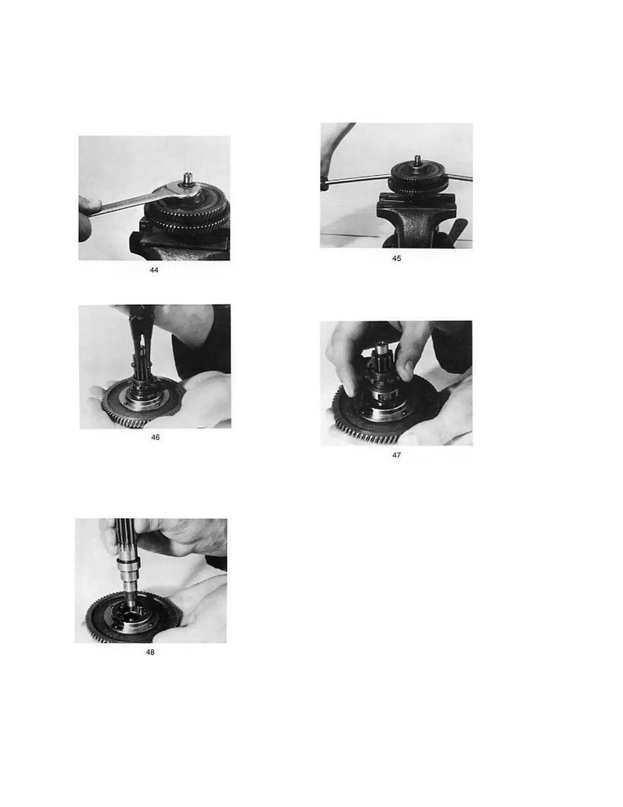
DISMANTLING, CHECKING, AND ASSEMBLING OF THE COUNTERSHAFT
Fix the countershaft into a vice and unscrew the
nut with a 19mm wrench (fig 44)
Remove the 2
nd
speed gear (fig 45)
Remove the circlip at the shaft’s toothing (fig 46)
Unfasten the wire spring and separate a small
chain sprocket with roller cage (fig 47)
Remove the 1
st
speed gear and shake the rollers
out (fig 48)
If troubles appear in the self-locking clutch,
consisting of rollers with 1
st
speed gear hub,
possible damage of the countershaft may be
repaired by grinding the bearing surface for
0.1mm at the most. When most rollers make small
hollows in the hub, the latter can be honed. If
hollows are rather large, the gear should be
replaced.
 Loading...