Connecting to power
12
EN
Connecting to
power
Connect LINK 300/310 to the vehicle power
supply with the standard vehicle voltage (12 V
/ 24 V). Do not connect to a voltage converter.
The three wires GND, IGN and PWR+ (supply
voltage) must be connected.
1. Connect the GND wire (brown) to ground
(clamp 31).
2. Fuse the PWR+ wire (red) and the IGN wire
(black) with one 2 A / fast blow fuse
(Technical data on page 27) each.
3. Connect the fused PWR+ wire (red) to the
carry current (clamp 30).
4. Then connect the fused IGN wire (black) to
ignition (clamp 15).
5. The IN1 wire can be used for multiple
purposes, e.g. connecting a digital
tachograph, reporting idle times or
recording other digital inputs. See Using
the digital input on page 19 for details. If
you do not make use of the input IN1,
please connect the IN1 wire (green/blue) to
GND.
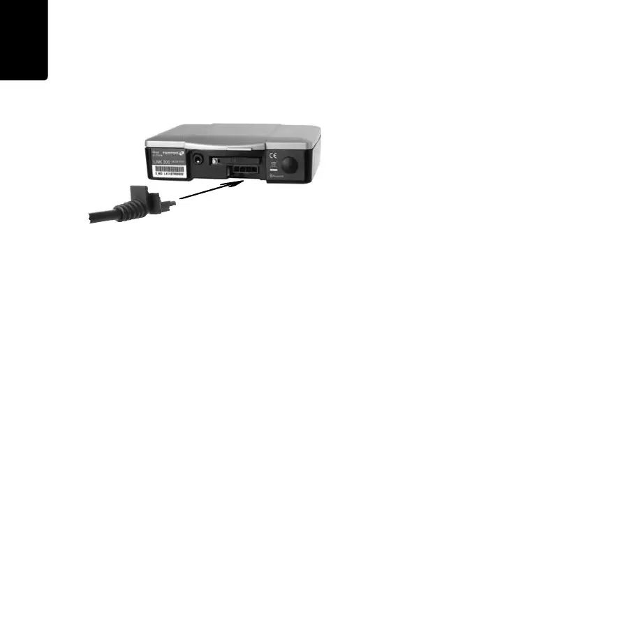
6. Insert the 4-pin plug into the power cable
connector.
IG_EN.book Page 12 Friday, June 10, 2011 3:26 PM