Using the digital input
20
EN
permissible input voltage is 30 Volts. Low/high
switching (increasing input voltage) typically
occurs at 2.8 Volts. High/low switching
(decreasing input voltage) typically occurs at
2.1 Volts. The hysteresis of 0.7 Volts is to avoid
rapid switching.
Interference voltages at the input IN 1 must
remain below 2 Volts. In order to guarantee
this, the input wire of the connecting cable
should never remain unconnected. If the input
IN 1 is not being used, the input wire must be
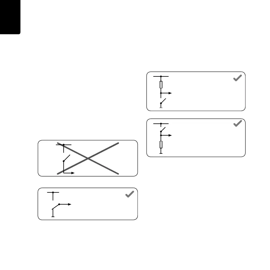
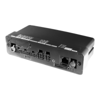
connected to ground (GND). To evaluate a
switch, this switch needs to be designed as a
change-over switch, switching input IN 1
between plus and minus (ground GND) of the
vehicle electrical system voltage (+9 ... 30V).
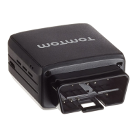
If no change-over switch is available, an
electric load (e.g. indicator light, resistor)
between input IN 1 and ground (GND) or
between input IN 1 and the vehicle voltage (+9
... 30V) can offer defined levels.
When using inductive loads, a free-wheeling
diode must be used in parallel with the load.
For more information and examples see http:/
/business.tomtom.com/in1
IN 1
(LINK 300/310)
+9 ... 30V
IN 1
(LINK 300/310)
+9 ... 30V
GND
Load resistor ≤ 10 KOhm
IN 1
(LINK 300/310)
+9 ... 30V
GND
Load resistor ≤ 10 KOhm
IN 1
(LINK 300/310)
+9 ... 30V
GND
IG_EN.book Page 20 Friday, June 10, 2011 3:26 PM