Do you have a question about the Topcon GREEN LABEL GTS-250 Series and is the answer not in the manual?
Provides essential precautions for safe and correct handling of the instrument.
Details critical safety warnings and prohibitions for product operation.
Covers warnings and cautions related to the instrument's power supply and battery.
Highlights warnings for safe setup and use of the tripod with the instrument.
Specifies user requirements and necessary protective equipment for operation.
Outlines limitations of manufacturer responsibility for product misuse or damage.
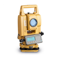
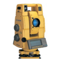
Illustrates and labels the main external parts of the instrument.
Describes the instrument's display screen, including its layout and features.
Details the function and purpose of each key on the instrument's control panel.
Explains the dynamic functions assigned to soft keys based on the displayed mode.
Describes how to access and use the Star key for instrument settings and options.
Details the purpose and function of the RS-232C serial port for data communication.
Provides a step-by-step guide for mounting, leveling, and centering the instrument on a tripod.
Explains how to turn on the instrument and initial display checks.
Details the battery indicator and its meaning for instrument operation.
Explains the automatic tilt correction feature for angle measurements.
Describes how to enable or disable tilt correction using soft keys.
Guides users on inputting alphanumeric characters for various settings and data entry.
Provides detailed steps and examples for entering alphanumeric characters.
Details the procedure for measuring horizontal and vertical angles to targets.
Explains how to switch between Right (HR) and Left (HL) horizontal angle modes.
Describes how to set and hold a specific horizontal angle value.
Guides on setting a desired horizontal angle using the instrument's keys.
Explains how to use the instrument in Vertical Angle Percent Grade mode.
Details the process for performing repetition angle measurements to improve accuracy.
Describes the buzzer function that signals 90° increments in horizontal angle.
Explains how the vertical angle is displayed in compass mode.
Explains how to set atmospheric correction based on temperature and pressure.
Details how to set the prism constant value for accurate distance measurements.
Guides on performing continuous distance measurements to a target.
Explains how to perform multiple-time or single distance measurements and view the average.
Describes different distance measurement modes (Fine, Tracking, Coarse) and their characteristics.
Details the stake-out procedure, calculating the difference between measured and target distances.
Introduces the four offset measurement modes for measuring inaccessible points.
Explains how to perform angle offset measurements for inaccessible targets.
Explains distance offset measurement for data collection, using offset horizontal distances.
Details plane offset measurement for data collection, used for measuring edges of planes.
Explains column offset measurement within data collection for finding column centers.
Guides on setting the instrument's occupied point coordinates and origin.
Explains how to set the instrument height, which is retained after power off.
Details how to set the target (prism) height for Z coordinate calculations.
Outlines the process for measuring unknown point coordinates using instrument and prism heights.
Introduces special measurement programs available within the instrument.
Explains the Remote Elevation Measurement (REM) procedure for inaccessible points.
Details the Missing Line Measurement (MLM) for calculating distances between points.
Explains how to set the Z coordinate of the occupied point using coordinate data files.
Details methods for calculating the area of a closed figure using coordinate data or measured data.
Explains how to measure coordinates relative to a determined line (point to line).
Describes how to set and apply the Grid Factor for coordinate calculations.
Explains how to adjust display illumination and reticle brightness.
Covers settings like minimum reading, auto power off, and tilt correction.
Describes setting ON/OFF for instrument error correction for angle measurement.
Explains how to turn the display heater on or off.
Details setting communication parameters for RS-232C connection to external devices.
Explains how to adjust the LCD display contrast level.
Introduces the ROAD menu operation for road survey applications.
Guides on inputting the starting point coordinates for road measurement.
Details how to input LINE, CURVE, SPIRAL, and POINT data for road surveys.
Explains how to search for previously input road data.
Guides on how to edit input road data.
Details how to set the Occupied Point and Backsight Point for road operations.
Explains the procedure for setting out points along a road alignment.
Describes how to select a file for Occupied and Backsight points.
Explains how to initialize (erase) ROAD data from internal memory.
Explains that collected data is memorized into files for storage and retrieval.
Discusses the impact of layout mode usage on the number of measurable points.
Covers initial steps before data collection, including file selection.
Guides on selecting or creating a file for storing collected measurement data.
Explains how to select a coordinate data file for use in data collection.
Details setting occupied and backsight points for data collection.
Provides a step-by-step guide for performing data collection measurements.
Explains how to search recorded data within the DATA COLLECT mode.
Guides on entering PCODE/ID using the PCODE Library for data collection.
Introduces offset measurement modes within data collection for inaccessible points.
Details the angle offset measurement procedure for data collection.
Explains distance offset measurement for data collection, using offset horizontal distances.
Details plane offset measurement for data collection, used for measuring edges of planes.
Explains column offset measurement within data collection for finding column centers.
Describes the automatic NEZ coordinate calculation and storage during data collection.
Explains point-to-line measurement for obtaining coordinates relative to a determined line.
Guides on entering and editing PCODE data in the PCODE Library.
Details settings for data collection parameters like distance mode and data confirmation.
Provides a flowchart for accessing and navigating the LAYOUT mode menus.
Covers initial setup steps before executing layout tasks.
Explains how to set and calculate the Grid Factor for layout operations.
Guides on selecting coordinate data files for use in the LAYOUT mode.
Details methods for setting the occupied point coordinates in LAYOUT mode.
Explains how to set the backsight point for layout operations.
Provides the procedure for executing a layout task, including angle and distance calculations.
Details layout execution using coordinate data of a point to line.
Covers methods for establishing new points when existing control is unavailable.
Explains the side shot method for setting new points when control points are not visible.
Details the resection method for calculating a new point's coordinate using known points.
Explains how to view the PT# list and associated coordinate data.
Manages files by checking status, renaming, and deleting.
Handles inputting, deleting, and managing coordinate and PCODE data.
Facilitates data transfer to/from computers and memory initialization.
Allows checking the internal memory status, including file and data counts.
Provides methods to search recorded file data in DATA COLLECT or LAYOUT modes.
Details searching measured data by file name, first/last data, or point number.
Explains how to edit point name, ID, PCODE, and height data in search mode.
Guides on searching coordinate data by file name and point number.
Explains how to search the PCODE Library by number or name.
Covers renaming files, searching data within files, and deleting files.
Details the procedure for renaming an existing file in the internal memory.
Explains how to search for data within a specific file.
Describes how to erase a file from the internal memory.
Guides on directly inputting coordinate data (NEZ, PTL) via keyboard.
Explains how to input PTL coordinate data directly from the keyboard.
Details how to erase specific coordinate data entries from a file.
Guides on entering and editing PCODE data in the PCODE Library.
Covers sending data to a computer and loading data from it.
Explains how to send measured or coordinate data files to a computer.
Details how to load coordinate and PCODE library data from a computer.
Guides on setting communication parameters like baud rate and parity for data transfer.
Explains how to initialize the internal memory, erasing file and PCODE data.
Explains how to input the prism constant correction value for accurate measurements.
Presents the formulas used for calculating atmospheric correction values.
Guides on setting atmospheric correction values by measuring temperature and pressure.
Explains how to directly input the atmospheric correction value (PPM).
Provides a chart to determine atmospheric correction values based on temperature and pressure.
Presents the formulas for distance calculation considering refraction and earth curvature.
Details information about the BT-G1W on-board battery.
Details the procedure for safely removing the on-board battery.
Provides instructions for charging the BT-G1W battery.
Explains the battery refresh procedure to restore capacity and improve operating time.
Guides on how to properly install the on-board battery into the instrument.
Details the procedure for detaching the instrument from the tribrach.
Explains how to attach the instrument to the tribrach.
Describes how to lock the tribrach locking lever to prevent accidental removal.
Lists and describes various selectable modes and settings for the instrument.
Provides examples and steps for setting various modes and options.
Explains how to check and adjust the instrument constant for measurement accuracy.
Details the procedure to check the alignment of the EDM and theodolite optical axes.
Covers general pointers and notes for adjusting theodolite functions and tribrach.
Guides on adjusting the vertical cross-hair to be perpendicular to the horizontal axis.
Explains the process of collimating the instrument for a straight line of sight.
Details how to check and adjust the optical plummet telescope for vertical axis alignment.
Guides on adjusting the vertical angle 0 datum for accurate coordinate origin determination.
Explains how to set the instrument constant value obtained from checks.
Details procedures for adjusting systematic errors like collimation and axis errors.
Describes the reference frequency check mode for EDM frequency testing.
Describes the interface cable for connecting the instrument to external devices.
Lists various prism holders, target plates, and pole adaptors for prism systems.
Details tribrach, optical plummet tribrach, and adaptors for prism systems.
Describes different prism units and the tripod accessory.
Details information about the BT-G1W on-board battery.
Lists target poles and prisms available for the system.
Details various prism holders, target plates, and adaptors.
Describes tribrachs, optical plummet tribrachs, and adaptors.
Describes prism units (single, 3, 9) and the tripod.
Errors related to insufficient points or impossible calculations.
Error displayed for REM measurement outside zenith/nadir range.
Indicates an abnormality in the EDM (distance measuring system).
Errors related to vertical angle setting, adjustment, or leveling.
Abnormality during data transmission between instruments.
Indicates an abnormality occurring with the internal memory system.
Errors related to file naming, capacity, or selection.
Errors indicating initialization failure or exceeding input limits.
Errors related to data availability or file selection.
Error in point-to-line measurement if the distance between points is less than 1m.
Errors in resection or new point input related to point data.
Errors occurring during measurement calculation or instrument tilt.
Indicates abnormality in angle measuring system, requiring repair if persistent.
Lists specifications for the instrument's telescope, including magnification and field of view.
Details measurement ranges and accuracy under different atmospheric conditions.
Specifies minimum display units and measurement times for various modes.
Defines ranges for atmospheric and prism constant corrections, and conversion factors.
Lists specifications for electronic angle measurement, including accuracy and reading.
Details specifications for automatic tilt correction and level sensitivity.
Provides specifications for the optical plummet telescope and instrument dimensions.
Specifies instrument weight and durability ratings for water, dust, and temperature.
Provides specifications for the BT-G1W battery, including capacity and operating time.
Lists specifications for the battery charger, including input voltage and recharging time.
Details FCC compliance information for Class B digital devices in the USA.
Notes Proposition 65 warnings for California, regarding chemical exposure.
Provides information on battery recycling in California and New York, USA.
States compliance with Canadian ICES-Class B digital apparatus regulations.
Indicates compliance with EU EMC Class B regulations for electromagnetic compatibility.
Refers to the WEEE Directive for EU member states, related to waste electrical equipment.
Indicates compliance with the EU Battery Directive for member states.
Notes compliance with Australia's C-Tick regulations.
States compliance with Korea's KC:ClassB regulations for electronic equipment.
Explains dual axis compensation for correcting errors from vertical axis inclination.
Provides precautions for battery charging and storage to maintain capacity and service life.
| Brand | Topcon |
|---|---|
| Model | GREEN LABEL GTS-250 Series |
| Category | Measuring Instruments |
| Language | English |