Technical Documentation
Page 17
4 Getting Started
4.1 Check the delivered parts
Please check whether all parts described in the scope of delivery have been delivered
correctly. For question or reclamation please contact the support team of Topcon
Electronics GmbH (opus-support@topcon.com).
5 Electrical installation OPUS B2/B2 Plus
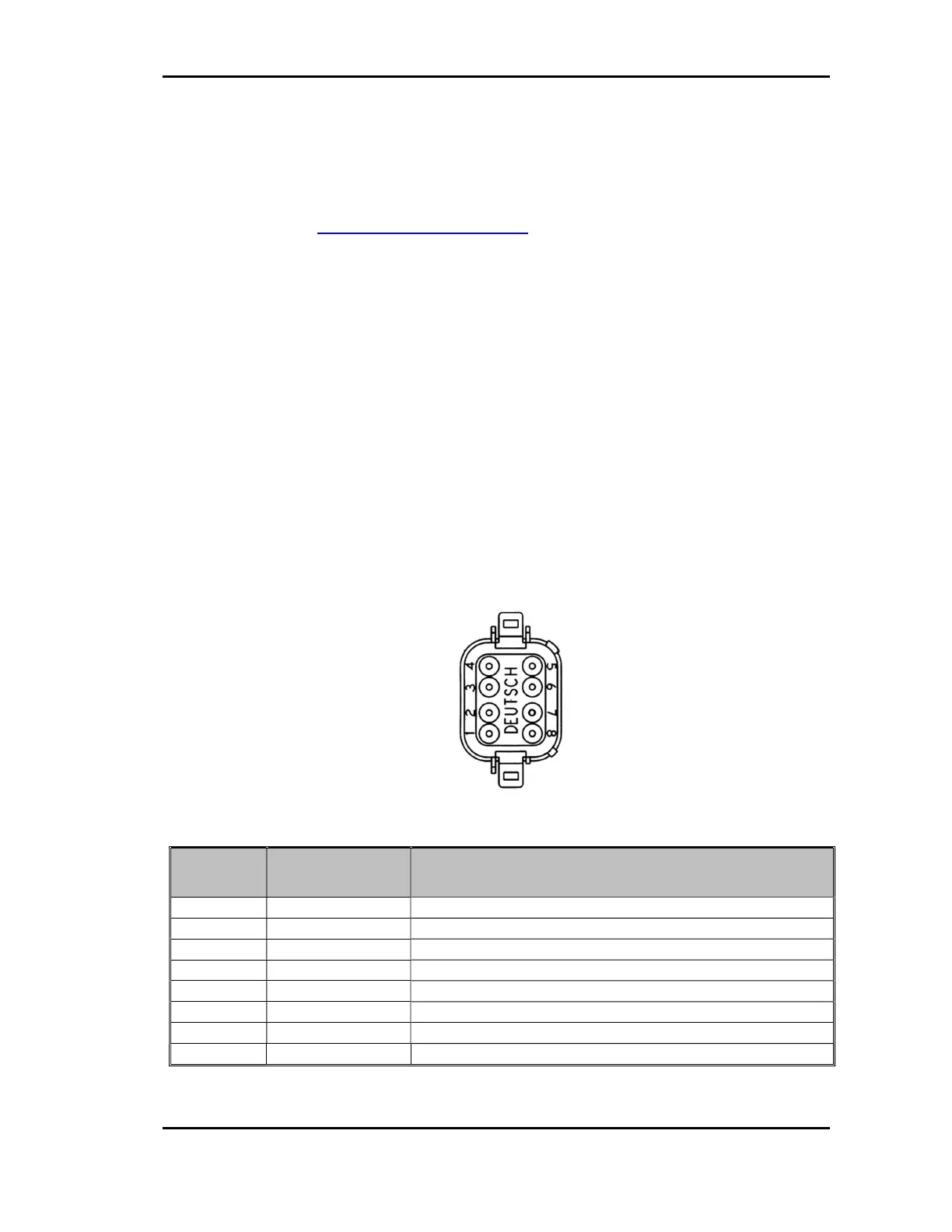
Below you find the pin out diagram of the OPUS B2/B2 Plus. The connectors (see fig.
3.3) are drawn as seen from the back side of the unit.
Please be aware that the existing pins and connectors depend on the hardware option
you ordered.
Please note that the OPUS B2/B2 Plus only represents one part of the entire CAN
network. Set-up and dimensioning of the network must be executed by specialized
personnel, and the information in this regard cannot be a component of this operating
manual.
Main connector pinout (in full option)
pin no. assignment description
ignition input; terminal 15
3 KL31 supply voltage -; terminal 31
4 KL30 supply voltage +; terminal 30
5 CAN 2 L CAN 2 low
6 CAN 2 H CAN 2 high
Please observe the following guidelines for set-up:
Main Connector
(Deutsch DT06-08SA)