Introduction
TRL-35 Operator’s Manual
1-2
TRL-35 LEDs
The four LEDs on the TRL-35 have the following indications for the
modem:
• Power LED
Solid green if power is connected to the modem.
• Sync LED
Solid red if a signal with a level exceeding the level required for
reception exists on the current radio channel frequency.
•Tx/Rx LED
Flashes green if the modem receives or transmits data over the
serial interface.
• Alarm LED
Solid red if an alarm is detected.
Standard Kit Cables and
Accessories
The TRL-35 (P/N 30-070004-01) bill of materials includes power and
communications cables, and the radio antenna for the modem. The
following table lists the cables included in the package.
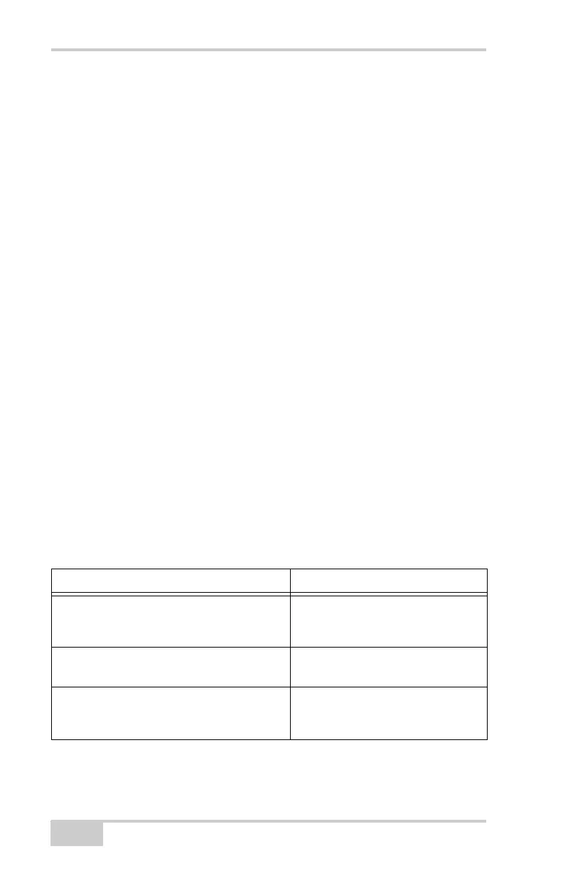
Table 1-1. Cables Included in TRL-35 Package
Part Number and Description Function
Power cable, 2-pin Alden connector to SAE
Topcon P/N 14-008110-01
Connects the TRL-35 and the power
supply via an SAE connection to
provide power to the modem.
Alligator clips to SAE cable
Topcon P/N 14-008025-01
Connects the modem to the external
power source.
TRL-35 Programming cable
Topcon P/N 14-008107-01LF
Connects to the DB-15 connector on
the TRL-35 and to a standard DB-9
connector to connect to a PC.