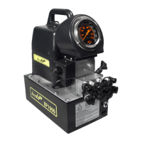
AIR MOTOR AND FILTER LUBRICATOR
The air motor is a precision built rotary motor. The top clearance (between rotor and bore) is .0015”.
The total end clearance (between the sides of the rotor and the end plates is .002”). The vanes take
up their own wear and will last 5,000-12,000 hours, depending upon speed, method of oiling, operat-
ing pressure, and lend itself to operating pressure above 100PSI (6.89 Bar-Metric). Allowing excess
moisture or foreign particles from the air line to enter the motor will nullify the guarantee.
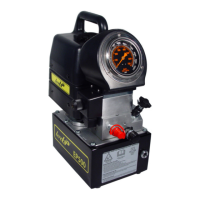
A moisture trap and lter has been installed in the air line ahead of motor. For efciency of output
and control of speed, use air line of not less then 1/2” pipe size. When coupling or connecting the
motor to a drive member, avoid any end or side thrust on the output shaft and especially DO NOT
HAMMER ON SHAFT.
The starting torque is more than the running torque and could vary depending on the position at
which the vanes stop in relation to the air intake port. The speed and torque can be regulated by
using a pressure regulator or a sim ple shut-off valve. Lubrication is necessary for the shaft seal,
and rust prevention. Each air powered pump is equipped with an automatic air line oiler set to feed
1-3 drops per minute. Use TorcUP Inc. antifreeze oil. Excessive mois ture in the line can cause rust
formation in the motor and might also cause ice to form in mufer due to expansion of air through
the motor.
NOTE: To adjust oiler drops, turn dial counter clockwise to “raise”, and clockwise to “lower”.
If the motor is sluggish or inefcient, try ushing with solvent in well ventilated area. Disconnect the air
line, again connect the air line and apply pressure slowly until there is no trace of solvent in exhaust
air. (Keep face away from exhaust air.) Check the mufer felts for grease, dirt, etc. If dirty, wash them
in solvent. Replace the felts and connect mufer. Relubricate the motor with a squirt of oil in the
chamber. If the vanes need replacing, or foreign particles are present in motor chamber, an experi-
enced mechanic may remove the end plate apposite the drive shaft end.
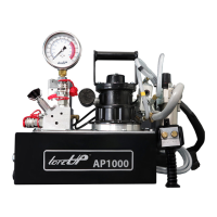
TECHNICAL SPECIFICATIONS
To prevent explosive hazard, do not pump combustible liquids or
vapors through these units.
AFTER COMPLETING THE JOB
Before disconnecting hoses, ttings, etc. rst be sure the tool is unloaded and retracted, then
disconnect the air line and shift the hydraulic controls several times to release system pressure.
Store the pump in a clean, dry area.
MAINTAIN OIL LEVEL
Check hydraulic oil level every 30 hours of operation (sight gauge should be completely covered in
oil when all tools are retracted. Add TorcUP oil (Model # AO1 – 1 gallon) when necessary. Oil level
should be no more than 1” from top of reservoir plate – with cylinders retracted and motor off.