EasyManua.ls Logo

TorcUP AP1000 - User Manual

TorcUP AP1000
26 pages
Print Icon
To Next Page IconTo Next Page
Loading...
OPERATION AND MAINTENANCE
MANUAL
Air Power Pack
MODELS AP1000, AP1000-Q
AP1000
1025 Conroy Place, Easton PA 18040 * U.S.A.
Phone: +1 610-250-5800 * Fax:+1 610-250-2700
Toll Free: 1-888-TORCUP-1
Email: sales@torcup.com * Website: www.torcup.com
Question and Answer IconNeed help?

Do you have a question about the TorcUP AP1000 and is the answer not in the manual?

Summary

SAFE AND CORRECT USE

USING THE TOOL

Guidelines for safe operation and handling of the tool during use.

Safety Information When Using The Tool

Essential safety precautions and personal protective equipment required for tool operation.

WARRANTY STATEMENT

Details the warranty coverage and limitations for TorcUP products.

SAFETY

Defines DANGER, WARNING, and CAUTION terms for hazard communication.

TECHNICAL SPECIFICATIONS

WORKING PRESSURE

Specifies the maximum working pressure and compatibility requirements for hydraulic equipment.

INSTALL VENT PLUG

Step-by-step instructions for installing the vent plug on the unit.

ADDING OIL

Guidance on how to add hydraulic oil to the reservoir.

PRESSURE TORQUE SETTING

Procedure for setting the pump pressure to achieve desired torque.

OPERATION PROCEDURES

PERIODIC MAINTENANCE

Schedule and procedures for routine maintenance of the hydraulic system.

CLEAN OIL INTAKE SCREEN ONCE A YEAR

Instructions for cleaning the oil intake screen for optimal pump performance.

FLUSH THE PUMP

Steps to follow for flushing the pump if contamination is suspected.

TROUBLE SHOOTING

Sporadic Tool Action

Solutions for issues where the tool operates intermittently or inconsistently.

Motor Will Not Start

Causes and fixes for the motor failing to start when activated.

Noisy Operation

Identifying and resolving causes of unusual noise during pump operation.

Pump Runs But Will Not Build Pressure

Troubleshooting steps for when the pump runs but fails to generate adequate pressure.

PARTS IDENTIFICATION

Valve Sub Assemblies

References to detailed diagrams and parts lists for valve sub-assemblies.

Pump Sub Assemblies and Sub-Components

Guides to identifying various sub-assemblies and components of the pump.

Common Components

Listing and identification of frequently used components across the system.

How to Identify Parts for Your Model

Instructions on how to use model numbers and date codes to identify specific parts.

COMMON COMPONENTS

AIR CONTROL VALVE #82

Identification of the air control valve and its part number.

ASSEMBLY NOTES

Important notes and torque specifications for assembling various components.

PUMP ASSEMBLY

PUMP ASSEMBLY (46335 SS) PUMP ASM.

Diagram and torque specifications for the main pump assembly.

PUMP SUB ASSEMBLY

PART# 43766 SS (UNLOADING PISTON ASM.)

Components and part numbers for the unloading piston assembly.

PART# 46336 SS (PISTON BLK ASM)

Diagram and part details for the piston block assembly.

VALVE ASSEMBLY

PART# 46297 SS (AIR SOLENOID 4 W;2 P)

Components and diagrams for the air solenoid valve assembly.

VALVE SUB ASSEMBLY

PART# 68963 SS (VALVE ADPT)

Parts list and diagram for the valve adapter sub-assembly.

PART# 41954 SS (AIR CYL ASSM)

Components and diagram for the air cylinder assembly.

PART# 46544 SS (AIR CONTROL VALVE ASSM.)

Diagram and torque notes for the air control valve assembly.

MANIFOLD ASSEMBLY

PART# 46292 SS MANIFOLD ASM.

Diagram and part list for the manifold assembly with torque specifications.

PART# 68999 SS INT. RELIEF ASM.

Components and part list for the internal relief valve assembly.

PENDANT ASSEMBLY

PART# 68799 SS (PENDANT ASSM.)

Detailed breakdown of the pendant assembly and its components.

RESERVOIR

1.5 GALLON RESERVOIR

Illustration and part list for the 1.5-gallon reservoir.

2.5 GALLON RESERVOIR

Illustration and part list for the 2.5-gallon reservoir.

Overview

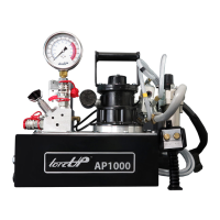
The TorcUP AP1000 is a heavy-duty air-powered hydraulic pump designed for industrial applications requiring high-pressure hydraulic force. It is suitable for use with various hydraulic tools such as torque wrenches, rams, and other accessories rated for 10,000 PSI (700kg/cm²) operating pressure.

Function Description

The AP1000 operates using a powerful 4HP industrial air motor, which runs on 60cfm/100PSI. It features a Quadra-Torc function (optional) and quick-connect couplers for ease of use. The pump is supplied with dual non-conductive high-pressure hoses, ensuring safe operation. Its primary function is to generate and control hydraulic pressure to operate connected tools for tasks such as tightening or loosening fasteners, lifting, or pressing. The air control buttons allow for precise advancement and retraction of hydraulic tools.

Important Technical Specifications

  • Air Motor: 4 HP, operating at 100 PSI / 60 cfm.
  • Maximum Working Pressure: 10,000 PSI (700 kg/cm²).
  • Usable Reservoir Capacity:
    • 1.5 Gallons (5.7 Liters) for the standard model.
    • Dimensions (L x W x H): 15.13 in (384.3 mm) x 19.09 in (484.88 mm) x 15.89 in (406.48 mm) x 5.94 in (150.88 mm) x 8.75 in (222.25 mm).
  • Flow Rate:
    • 700 cu. in./min. at 1,100 PSI.
    • 55 cu. in./min. at 10,000 PSI.
  • Weight (without oil): 63.75 lbs (28.92 kg).
  • Valve Style: Torque, Auto Advance/Retract.
  • Control: Motor/Solenoid Control.
  • Warranty: 13 Month Warranty.

Usage Features

  • Air Control Buttons: The pump is equipped with "RUN" and "STOP" buttons. The "RUN" button activates the air solenoid and turns on the motor, while releasing it and pressing the "STOP" button turns off the motor.
  • Pressure Torque Setting: The pump allows for precise pressure adjustment to achieve desired torque values. This involves loosening a lock nut, backing out the relief valve, turning on the pump, and then adjusting the relief valve clockwise to increase pressure or counter-clockwise to decrease it. The lock nut must be tightened to maintain the setting.
  • Hydraulic Tool Connection: Tools, hoses, and accessories must be rated at 10,000 PSI. Quick-disconnect couplings should be fully engaged, and threaded connections must be securely tightened and leak-free, using 1.5 wraps of Teflon tape on threads (leaving the first complete thread free).
  • Safety Features: The manual emphasizes the importance of wearing personal protective gear (eye and ear protection, safety shoes, hard hat, gloves, coveralls), maintaining a balanced stance, and avoiding overreaching. It warns against using damaged hoses, exceeding maximum pressure, and carrying the tool by the hose. The torque reaction arm must be positioned against a positive stop to prevent pinching.
  • Environmental Considerations: The pump should be kept away from flames and excessive heat (above 65°C / 170°F) to prevent seal damage and fluid leaks. Hoses and cylinders should be protected from weld spatter.

Maintenance Features

  • Oil Level Maintenance: Hydraulic oil level should be checked every 30 hours of operation, ensuring the sight gauge is completely covered when tools are retracted. TorcUP oil (Model # AO1 – 1 gallon) should be added as necessary, keeping the level no more than 1 inch from the top of the reservoir plate with cylinders retracted and the motor off.
  • Periodic Maintenance:
    • Hydraulic Oil Change: The hydraulic oil should be completely changed twice a year.
    • Intake Screen and Magnet Cleaning: The intake screen and magnet (located in the reservoir) should be cleaned twice a year.
    • External Oil Filter Change: If equipped, the external oil filter should be changed twice a year.
    • Increased Frequency: Oil changes should be more frequent in dusty environments or when the oil has been overheated.
  • Clean Oil Intake Screen: Once a year, the reservoir plate bolts should be loosened, and the pump unit lifted off the reservoir to access and clean the intake screen with nonflammable solvent.
  • Flushing the Pump: If contamination, sludge, or deposits are suspected, the pump should be thoroughly flushed. This involves draining the old oil, cleaning the reservoir, refilling with flushing oil, running the pump for 1-2 minutes without load, then draining the flushing oil, re-cleaning the reservoir, and finally refilling with TorcUP hydraulic oil.
  • Air Motor and Filter Lubricator: The air motor is a precision-built rotary motor. The air line oiler is set to feed 1-3 drops per minute of TorcUP Inc. antifreeze oil for lubrication and rust prevention. The oiler drops can be adjusted by turning the dial. If the motor is sluggish, it can be flushed with solvent in a well-ventilated area. Muffler felts should be checked and cleaned if dirty.
  • Troubleshooting: The manual provides a troubleshooting guide for common issues such as sporadic tool action (air in hydraulic system, low oil level), motor not starting (water in air line, low air pressure, motor malfunction), noisy operation (air in system, clogged intake screen), pump oil overheating (high-pressure leakage, low oil level), and pump running but not building pressure (pump not primed, relief valve setting, defective control valve, clogged intake screen, low oil, high oil viscosity, small air line, low air pressure).

TorcUP AP1000 Specifications

General IconGeneral
BrandTorcUP
ModelAP1000
CategoryWater Pump
LanguageEnglish

Related product manuals