g375691
Figure9
1.Capscrew3.Flangelocknut(3/8inch)
2.Righttab(Carrierframe)
4.Assemblethecapscrewoftheturfcompensation
springtotherighttabofthecarrierframe(Figure
10)withtheangelocknut(3/8inch).
g375694
Figure10
1.Flangelocknut(3/8inch)3.Capscrew
2.Righttab(Carrierframe)
5.Alignthestudsofthelefthoseguidewith
theholesinthecutting-unitframeandthe
turf-compensatorbracket(Figure11).
Note:Thesupportloopofthehoseguidealigns
towardthecenterlineofthemachine.
g375687
Figure11
1.Turf-compensatorbracket3.Stud(hoseguide)
2.Flangelocknut(3/8inch)
4.Inboard
6.Assemblethehoseguideandturf-compensator
brackettothecutting-unitframewiththe2ange
locknuts(3/8inch).
7.T orquethelocknutsandboltsto37to45N∙m
(27to33ft-lb).
InstallingtheHoseGuide
CuttingUnits5
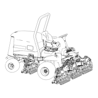
g375672
Figure12
1.Cuttingunit15.Cuttingunit5
2.Cuttingunit2
6.Reelmotor
3.Cuttingunit3
7.Weight
4.Cuttingunit4
1.Ifthehairpinisinstalledintherearholeofthe
compensation-springrod—removethehairpin
andinsertitintheholenexttothebracket
(Figure12).
13