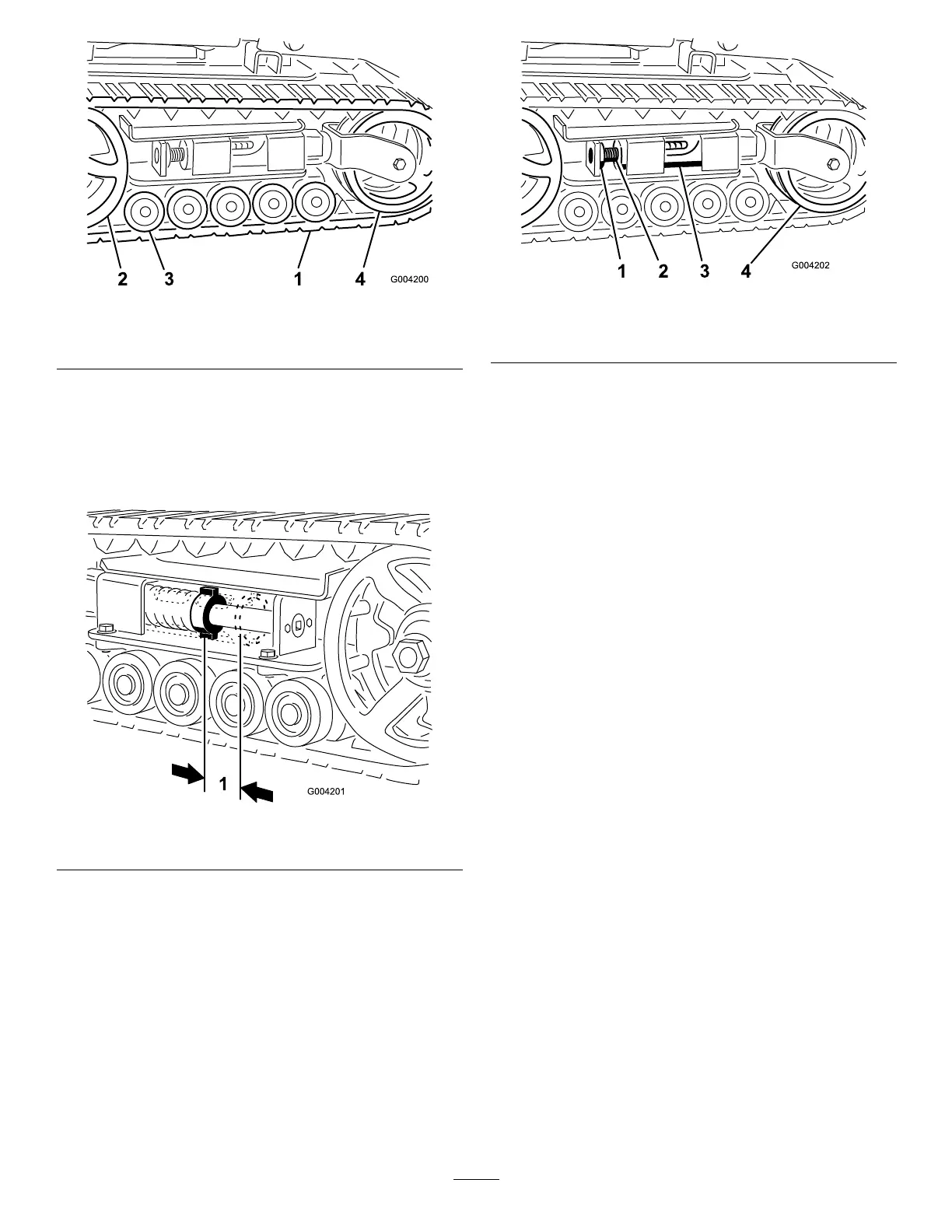
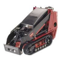
Figure39
1.Track3.Roadwheels
2.Drivesprocket4.Tensionwheel
AdjustingtheTrackTension
Thereshouldbe2-3/4inches(7cm)betweenthetension
nutandthebackofthetensiontube(Figure40).Ifnot,
adjustthetracktensionusingthefollowingprocedure:
Figure40
1.2-3/4inches(7cm)
1.Lowertheloaderarms,stoptheengine,andremove
thekey.
2.Lift/supportthesideoftheunittobeworkedonso
thatthetrackisoffoftheground.
3.Removethelockingboltandnut(Figure41).
Figure41
1.Lockingbolt3.Tensiontube
2.Tensioningscrew4.Tensionwheel
4.Usinga1/2inchdrivesocketwrench(Figure42),
turnthetensioningscrewcounter-clockwiseuntilthe
distancebetweenthetensionnutandthebackofthe
tensiontube(Figure40)is2-3/4inches(7cm).
5.Aligntheclosestnotchinthetensionscrewtothe
lockingboltholeandsecurethescrewwiththe
lockingboltandnut(Figure41).
6.Lowerthetractionunittotheground.
ReplacingtheTracks(Models22321
and22321G)
Whenthetracksarebadlyworn,replacethem.
1.Lowertheloaderarms,stoptheengine,andremove
thekey.
2.Lift/supportthesideoftheunittobeworkedon
sothatthetrackis3to4inches(7.6to10cm)off
oftheground.
3.Removethelockingboltandnut(Figure41).
4.Usinga1/2inchdrivesocketwrench,release
thedrivetensionbyturningthetensioningscrew
clockwise(Figure41andFigure42).
32