GROUND DRIVE & TINE SYSTEMS
5-3
Toro 30” Aerator Service Manual
5
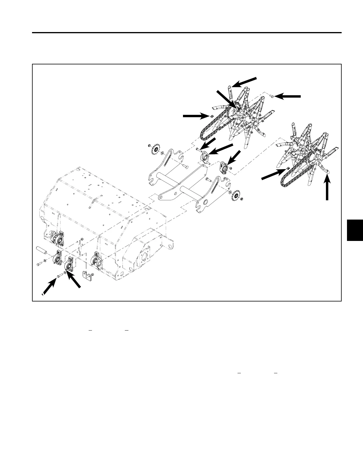
Fig. 179 subsystem aerator asm
Aerator Assembly
(Fig. 179)
E. Install the connecting links so the cover plate and
spring clip are to the outside of the machine. Install
spring clip so opening is away from forward direction
of rotation.
F. Grease location.
G. Zerk on trail arm pivot bearings must face down
away from the engine mounting plate.
H. Torque to 27 + 3 ft-lbs. (37 + 4 Nm)
A. Apply Loctite
®
242 to setscrews (4) and screws (4)
and tighten to 27 + 3 ft-lbs. (37 + 4 Nm).
B. Adjust idler position to allow a maximum of 3/8” of
chain movement.
C. Zerk on tine shaft bearings must face rear of unit.
D. Adjust tine shaft outward until the spyder contacts
the outer tine shaft bearings. Slide locking collar up
to the tine idler and slide tine idler up to center tine
shaft bearing. Use Loctite 243 for lock collar screws.
Tighten locking collar to tine shaft. Torque to 12-14
ft-lbs. (16-19 Nm). Tine idler must turn freely.
A
G
B
C
H
A/H
B
E
E
F
D
D

 Loading...