12
4
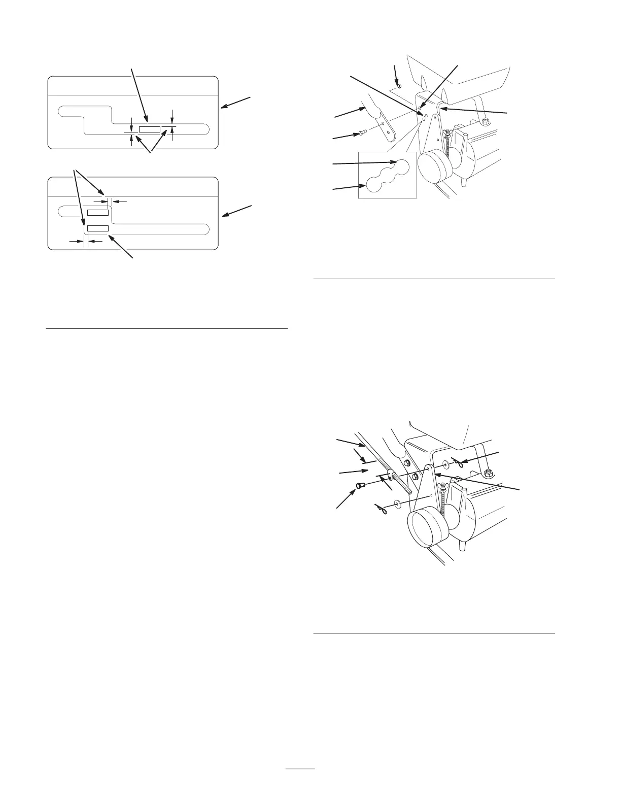
Rear View
1
m–5458
4
3
2
2
Figure 5
1. Shift lever, 2nd gear
2. Control panel
3. Shift lever, neutral
4. Equal distance
Installing the Upper Handle
1. Align upper handle with upper mounting holes in rear
frame (Fig. 6).
2. Secure each upper mounting hole with a flange bolt
(3/8 x 1 in.) and flange nut (Fig. 6). Torque bolts to
25 ft.–lb. (34 Nm).
3. Select high, medium or low position for the lower
mounting hole (Fig. 6). This allows the upper handle
to be adjusted to the user’s height preference.
4. Secure each lower mounting hole with a flange bolt
(3/8 x 1 in.) and flange nut (Fig. 6). Torque bolts to
25 ft.–lb. (34 Nm).
1
2
3
4
m–5317
8
7
5
6
Figure 6
1. Upper handle
2. Rear frame
3. Flange bolt, 3/8 x 1 in.
4. Flange nut, 3/8 in.
5. Upper mounting hole
6. Lower mounting holes
7. Low position
8. High position
Installing the Control Rods
1. Thread rod fittings equal distance onto each control
rod. For a starting point, thread fittings on
approximately 1–3/4 in. (44 mm) from the start of the
threads (Fig. 7).
2. Slide clevis pins through rod fittings and mounting
holes in idler brackets (from outside) (Fig. 7). Secure
with washers and hairpin cotters (Fig. 7).
1
3
2
4
4
m–5316
Figure 7
1. Control rod and fitting
2. 1–3/4in. (44 mm)
3. Idler bracket
4. Clevis pin, washer and
hairpin cotter