31
mower. Move the thrust washers from the bottom of
the mounting tube to the top to lower the front of the
mower. (Fig. 47).
5. Check the side-to-side leveling of the cutting unit.
3
4
1
5
2
2
m–2504
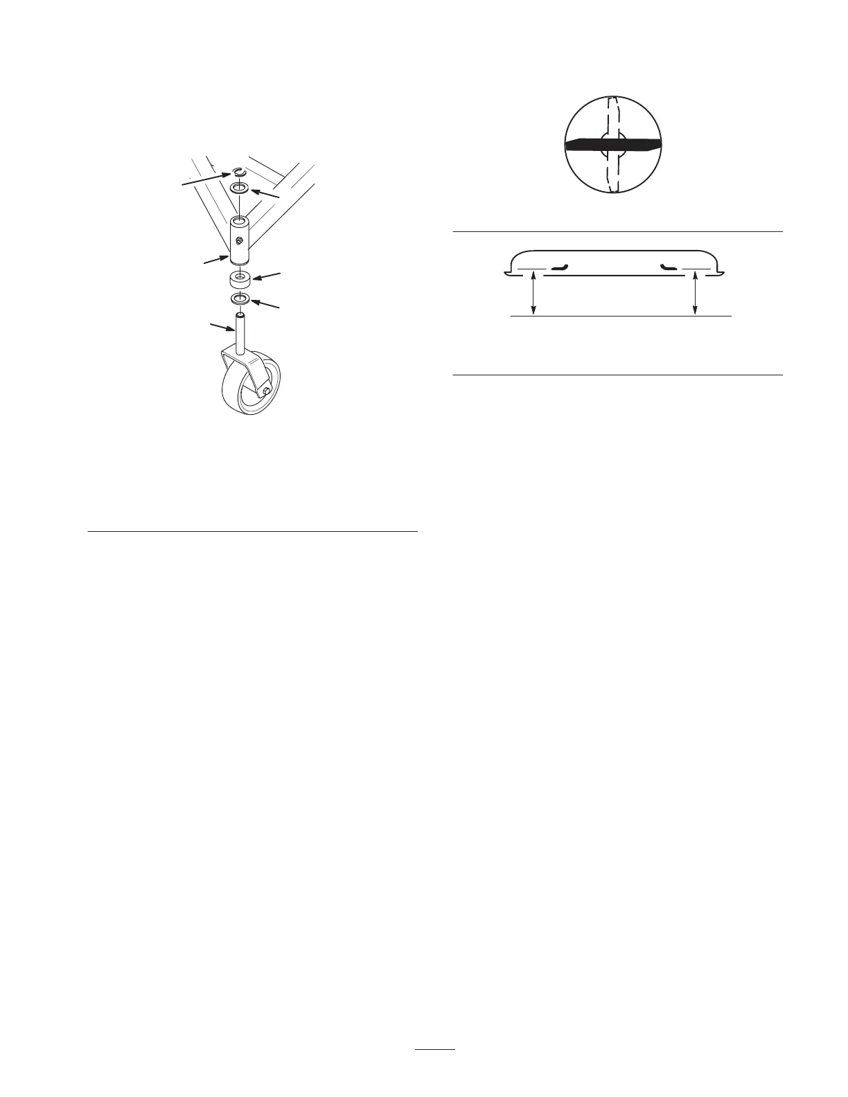
Figure 47
1. Retaining ring
2. Thrust washer (locate as
required)
3. Carrier frame mounting
tube
4. Spacer
5. Castor wheel fork
Setting the Side to Side Level
1. Position the blade side-to-side (Fig. 48).
2. Measure at the A and B locations (Fig. 48) from a
level surface to the cutting edges of the blade
(Fig. 49).
The difference between measurements A and B should
be no more than 1/4 in. (6 mm).
Front
m–2620
AB
Figure 48
m–2619
MEASURE FROM CUTTING EDGE TO A LEVEL SURFACE
Figure 49
3. To change the side-to-side leveling, move the thrust
washers on one castor wheel fork only. Move the thrust
washer(s) from the top of the carrier frame mounting
tube to the bottom to raise the corresponding side of
the mower. Move the thrust washer(s) from the bottom
of the mounting tube to the top to lower the
corresponding side of the mower. (Fig. 47).
4. Check the front-to-rear pitch of the cutting unit.
Replacing the Castor Wheel
Fork Bushings
The castor wheel forks are mounted in bushings pressed
into the top and bottom of the carrier frame mounting
tubes. To check the bushings, move the castor forks back
and forth and side-to-side. If a castor fork is loose, replace
the bushings.
1. Disengage the blade control (PTO), set the parking
brake, stop the engine, remove the key, and disconnect
the spark plug wire from the spark plug.
2. Raise the cutting unit so the castor wheels are off the
floor, then block up the front of the mower with jack
stands.
3. Remove the retaining ring and thrust washer(s) from
the top of the castor wheel fork (Fig. 50).