CheckingtheTirePressure
ServiceInterval:Beforeeachuseordaily
Thetiresareover-inatedforshipping.Therefore,
releasesomeoftheairtoreducethepressure.The
correctairpressureinthefrontandreartiresis
172-207kPa(25-30psi).
Important:Maintainevenpressureinalltiresto
ensureagoodquality-of-cutandpropermachine
performance.Also,theAutomaticTractionAssist
willnotworkproperlywithimpropertirepressure.
Donotunder-inate.Replacewornordamaged
tireswithgenuineTorotiresthatarecorrectly
sizedforthismachine.
CheckingtheTorqueoftheWheel
NutsorBolts
ServiceInterval:Aftertherst10hours
Every200hours
WARNING
Failuretomaintainpropertorqueofthewheel
nutscouldresultinfailureorlossofwheel
andmayresultinpersonalinjury.
Torquethefrontwheelnutsandrearbolts
to115to136N⋅ ⋅
⋅
m(85to100ft.-lb.)after1-4
hoursofoperationandagainafter10hoursof
operation.Torqueevery200hoursthereafter.
AdjustingtheHeight-of-Cut
FrontCuttingUnit
Theheight-of-cutisadjustablefrom25to127mm(1
to5inches)in13mm(1/2inch)increments.T oadjust
theheight-of-cutonthefrontcuttingunit,position
thecastorwheelaxlesintheupperorlowerholesof
thecastorforks,addorremoveanequalnumberof
spacersfromthecastorforks,andsecuretherear
chaintothedesiredhole.
1.Starttheengineandraisethecuttingunitsso
thattheheight-of-cutcanbechanged.Stopthe
engineandremovethekeyafterthecuttingunit
israised.
2.Positionthecastorwheelaxlesinthesame
holesinallcastorforks.Refertothefollowing
charttodeterminethecorrectholesforthe
setting.
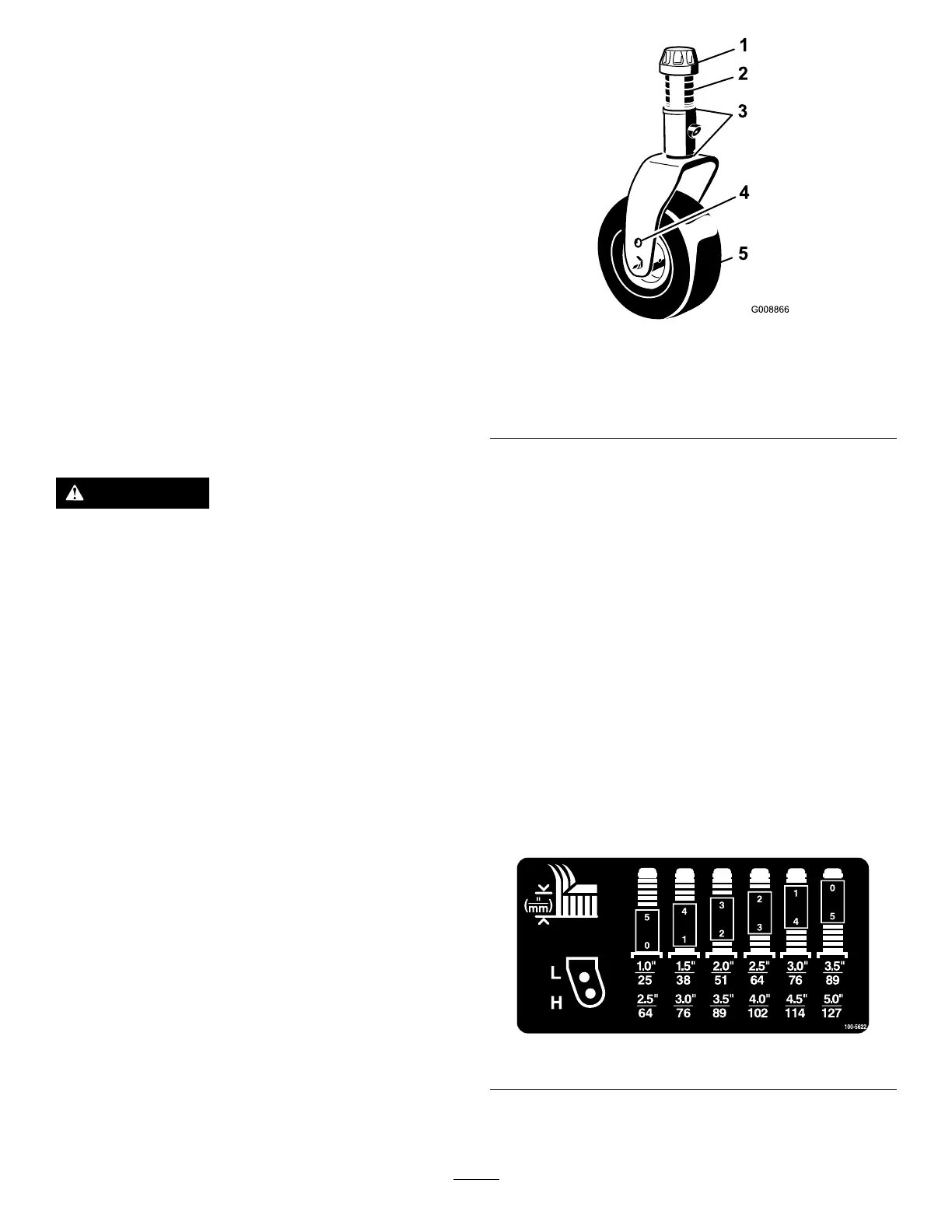
g008866
Figure18
1.Tensioningcap4.Topaxlemountinghole
2.Spacers5.Castorwheel
3.Shims
Note:Whenoperatingin64mm(2-1/2inch)
heightofcutorhigher,theaxleboltmustbe
installedinthelowercastorforkholetoprevent
grassbuildupbetweenthewheelandthefork.
Whenoperatinginheightofcutslowerthan
64mm(2-1/2inches)andgrassbuildupis
detected,reversethemachinesdirectiontopull
anyclippingsawayfromthewheel/forkarea.
3.Removethetensioningcapfromthespindle
shaft(Figure18)andslidethespindleoutofthe
castorarm.Putthe2shims(3mm[1/8inch])
ontothespindleshaftastheywereoriginally
installed.Theseshimsarerequiredtoachievea
levelacrosstheentirewidthofthecuttingunits.
Slidetheappropriatenumberof13mm(1/2
inch)spacers(refertothechartbelow)ontothe
spindleshafttogetthedesiredheight-of-cut;
thenslidethewasherontotheshaft.
Refertothefollowingcharttodeterminethe
combinationsofspacersforthesetting:
decal100-5622nc
Figure19
4.Pushthecastorspindlethroughthefrontcastor
arm.Installtheshims(astheywereoriginally
29