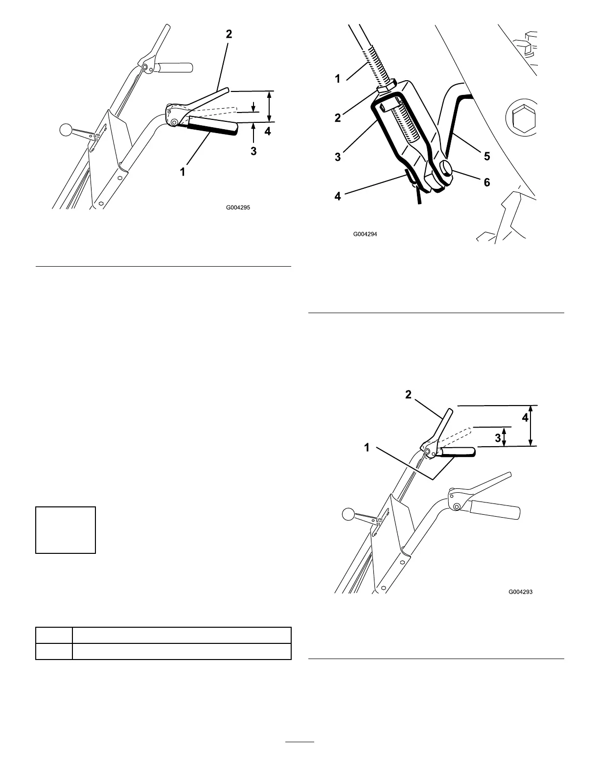
Figure7
1.Handgrip
3.1to2inches(3to5cm)
2.Tractioncontrollever
4.4-1/2inches(11.4cm)
3.Tightenthe2angenutsuntiltheyarengertight.
4.Movethespeedselectorlever(Figure14)intothird
gear.
Note:Ifthespeedselectorleverdoesnotmoveinto
thirdgear,adjustthespeedselectorbeforecontinuing.
RefertoAdjustingtheSpeedSelectorinMaintenance.
5.Slowlypullthemachinebackwardwhileslowlypressing
thetractioncontrollevertowardthehandgrip.
Note:Theadjustmentiscorrectwhenthewheelsstop
rollingbackwardandthedistancebetweenthetopof
thehandgripandthebottomofthetractioncontrol
leveris1to2inches(3to5cm)asshownin
Figure7.
6.Adjustthe2angenuts,ifnecessary,toobtainthe
properdistancebetweenthetopofthehandgripand
thebottomofthetractioncontrollever.
7.Tightentheangenutssecurely.
4
InstallingtheAuger/Impeller
DriveControlLinkage
Partsneededforthisprocedure:
1
Clevispin
1
Cotterpin
Procedure
1.Loosenthejamnutabovetheclevisontheupper
controlrod(
Figure8).
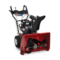
Figure8
1.Uppercontrolrod
4.Cotterpin
2.Jamnut5.Lowercontrolrod
3.Clevis6.Clevispin
2.Aligntheholesintheclevisandthelowercontrolrod
andinserttheclevispin(Figure8).
3.Checkthedistancebetweenthetopofthehandgrip
andthebottomoftheauger/impellerdrivecontrol
lever(
Figure9).
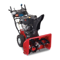
Figure9
1.Handgrip
3.1to2inches(3to5cm)
2.Auger/impellercontrol
lever
4.5inches(12.7cm)
Note:Thedistanceshouldbeapproximately5inches
(12.7cm).
4.Presstheauger/impellerdrivecontrolleverslowly
towardthehandgrip.
11