29
2. Carefully tip the mower over.
3. Remove the bolt (5/8 in. wrench), curved washer,
retainer and blade (Fig. 34). A block of wood may be
wedged between the blade and the mower to lock the
blade when you are removing the bolt.
m-1886
1
2
3
4
5
Figure 34
1. Bolt
2. Retainer
3. Blade
4. Spindle
5. Curved washer
4. Inspect all parts. If damage is noticed, install new parts.
Sharpening the Blades
1. Use a file to sharpen the cutting edge at both ends of the
blade (Fig. 35). Maintain the original angle. The blade
retains its balance if the same amount of material is
removed from both cutting edges.
m-1854
1
Figure 35
1. Sharpen at original angle
2. Check the balance of the blade by putting it on a blade
balancer (Fig. 36). If the blade stays in a horizontal
position, the blade is balanced and can be used. If the
blade is not balanced, file some metal off of the back
side of the blade. Repeat this procedure until the blade
is balanced.
m-1855
1
2
Figure 36
1. Blade 2. Balancer
Installing the Blades
1. Install the blade, blade retainer, curved washer (cupped
side toward blade), and the blade bolt (Fig. 34).
Important The curved part of the blade must be
pointing toward the inside of the mower to ensure proper
cutting.
2. Tighten the blade bolt to 45 to 60 ft-lb (61 to 81 N⋅m).
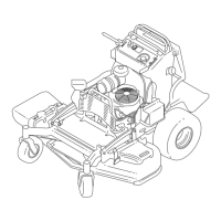
Removing the Mower
1. Park the tractor on a level surface.
2. Disengage the PTO and set the parking brake.
3. Stop the engine, remove the key, and wait for all
moving parts to stop before leaving the operating
position.
4. Move the height-of-cut lever into the D notch.
5. Remove the height-of-cut lift assist spring from the
retaining bolt (Fig. 37). The spring is between the frame
and the right rear wheel.
Note: Use the spring tool provided with the machine.
1
2
3
m-1851
Figure 37
1. Spring
2. Bolt
3. Spring tool
When you remove the mower, the spring-tensioned
height-of-cut lever could suddenly release and
injure you or someone else.
Move the height-of-cut lever to the “D” position
and remove the height-of-cut assist spring to
release the spring tension.
Caution
6. Move the height-of-cut lever into the “A” notch.