InstallingtheBattery
1.Positionthebatteryinthetraywiththeterminalposts
oppositefromthehydraulictank(Figure47).
2.Installthepositive(red)batterycabletopositive(+)
batteryterminal.
3.Installthenegative(black)batterycableandground
wiretothenegative(-)batteryterminal.
4.Securethecableswith2bolts,2washers,and2locknuts
(Figure47).
5.Slidetheredterminalbootontothepositive(red)
batterypost.
6.Installtheclampandsecureitwiththewingnut(Figure
47).
ChargingtheBattery
WARNING
Chargingthebatteryproducesgassesthatcan
explode.
Neversmokenearthebatteryandkeepsparksand
amesawayfrombattery.
Important:Alwayskeepthebatteryfullycharged
(1.265specicgravity).Thisisespeciallyimportantto
preventbatterydamagewhenthetemperatureisbelow
0°C(32°F).
1.Chargebatteryfor10to15minutesat25to30amps
or30minutesat10amps.
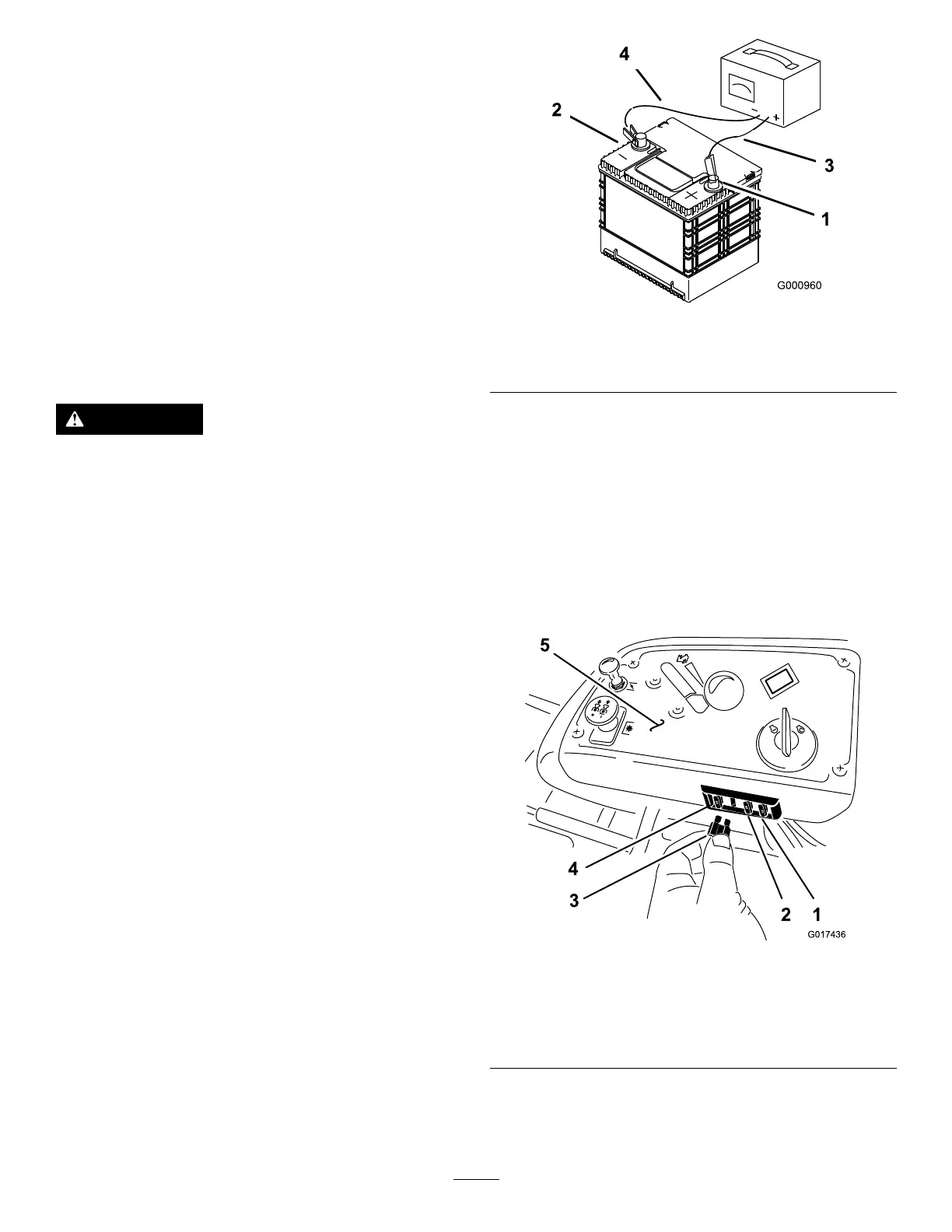
2.Whenthebatteryisfullycharged,unplugthecharger
fromtheelectricaloutlet,thendisconnectthecharger
leadsfromthebatteryposts(Figure48).
3.Installthebatteryinthemachineandconnectthe
batterycables;refertoInstallingtheBattery(page39).
Note:Donotrunthemachinewiththebattery
disconnected,electricaldamagemayoccur.
Figure48
1.Positivebatterypost
3.Red(+)chargerlead
2.Negativebatterypost
4.Black(-)chargerlead
ServicingtheFuses
Theelectricalsystemisprotectedbyfuses.Itrequires
nomaintenance,however,ifafuseblowscheckthe
component/circuitforamalfunctionorshort.
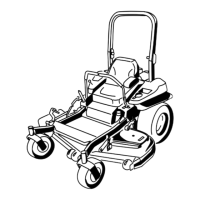
1.Thefusesarelocatedonrighthandconsolenextto
theseat(Figure49).
2.Toreplacethefuses,pulloutonthefusetoremoveit.
3.Installanewfuse(Figure49).
Figure49
1.Optional
accesory—15amp
4.Main—25amp
2.Charge—25amp5.Console
3.PTO—10amp
39