ControlsSystem
Maintenance
AdjustingtheControl-Handle
Position
Thereare2heightpositionsforthecontrollevers—highand
low .Removetheboltstoadjusttheheightfortheoperator.
1.DisengagethePTO,movethemotion-controlleversto
theneutral-lockedposition,andsettheparkingbrake.
2.Stoptheengine,removethekey,andwaitforallmoving
partstostopbeforeleavingtheoperatingposition.
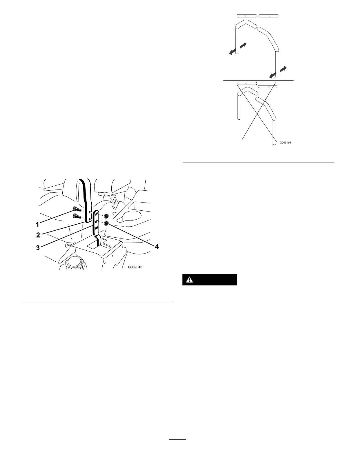
3.Loosentheboltsandangenutsinstalledinthelevers
(Figure61).
4.Aligntheleversinthefront-to-rearpositionby
bringingtheleverstogethertotheneutralposition,and
slidethemuntiltheyarealigned,thentightenthebolts
(Figure62).
Figure61
1.Bolt
3.Controllever
2.Handle4.Nut
Figure62
5.Iftheendsofthelevershitagainsteachother,refer
toAdjustingtheMotionControlNeutral-LockPivot
(page47).
6.Repeattoadjustthecontrollevers.
AdjustingtheMotion-Control
Linkage
Locatedoneithersideofthefueltank,belowtheseatarethe
pump-controllinkages.Rotatingthepumplinkagewitha
1/2inchwrenchallowsne-tuningadjustments,sothatthe
machinedoesnotmoveinneutral.Anyadjustmentsshould
bemadeforneutralpositioningonly.
WARNING
Theenginemustberunningandthedrivewheels
mustbeturning,sothemotion-controladjustment
canbeperformed.Contactwithmovingpartsor
hotsurfacesmaycausepersonalinjury.
Keepyourngers,hands,andclothingclearof
rotatingcomponentsandhotsurfaces.
1.Priortostartingtheengine,pushthedeck-liftpedal,
removetheheight-of-cutpin,andlowerthedeckto
theground.
2.Raisetherearofmachineupandsupportwithjack
stands(orequivalentsupport)justhighenoughto
allowthedrivewheelstoturnfreely.
3.Movetheseattothefurthestrearpositiontoexpose
thefrontnuts.
4.Loosenthefrontnuts.
Note:Thenutsdonotneedtoberemoved.
45