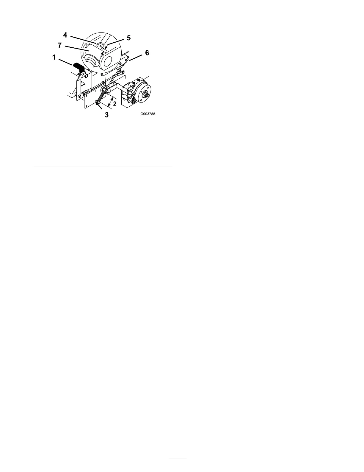
Figure 52
1. Brake lever
5. 3/16–1/4 inch (5–7 mm)
2. Spring (2-3/4 inches/70
mm)
6. Jam nut and yoke
3. Adjusting nuts
7. Trunnion
4. Collar on brake rod
3. If adjustment is necessar y , loosen the jam n ut
belo w the spring and tighten the n ut directly
belo w the y ok e ( Figure 52 ). T ur n the n ut until
the cor rect measurement is obtained. Tighten
the tw o n uts tog ether and re peat on opposite
side of unit.
4. T ur n n uts cloc kwise to shor ten spring length
and tur n counter -cloc kwise to lengthen the
spring .
5. Eng ag e parking brak e , lev er up .
6. Measure the distance betw een the tr unnion
roller and the collar on brak e rod.
T he measurement should be 3/16-1/4 inc h
(5-7 mm) ( Figure 52 ).
7. If adjustment is necessar y , loosen the jam n ut
directly belo w the y ok e . T ur n the bottom rod
until the cor rect measurement is obtained
( Figure 52 ). Tighten jam n ut at y ok e
Belt Maintenance
Inspecting the Belts
Inspect all belts ev er y 100 hours .
Chec k belts for crac ks , fra yed edg es , bur n marks
or any other damag e . R e place damag ed belts .
Replacing the Mower Belt
Squealing when the belt is rotating, blades slipping
when cutting g rass , fra yed belt edg es , bur n marks
and crac ks are signs of a w or n mo w er belt. R e place
the mo w er belt if any of these conditions are
evident.
1. Diseng ag e the PTO , mo v e the motion control
lev ers to the neutral loc k ed position, and set
the parking brak e .
2. Stop the engine , remo v e the k ey , and w ait for
all mo ving par ts to stop before lea ving the
operating position.
3. R emo v e the bolts holding the belt co v ers in
place and remo v e the belt co v ers .
4. Loosen the n ut securing the idler plate and
mo v e the idler plate to reliev e the belt tension
on the idler pulley ( Figure 53 ).
5. R emo v e the n ut, w asher and belt guide from
the rear left side pulley .
6. R emo v e the mo w er belt from the belt guides
and remo v e the belt ( Figure 53 ).
7. Install the new mo w er belt around the mo w er
spindle pulleys , mo w er idler pulley , into the
belt guides , into rear idler ar m assembly , and
the clutc h ( Figure 53 ).
8. Install the belt guide with a w asher and n ut
onto the rear left side pulley .
Note: Chec k the amount of twist in the belt
betw een the pulleys . Ensure it is only what is
specified in Figure 53 .
42