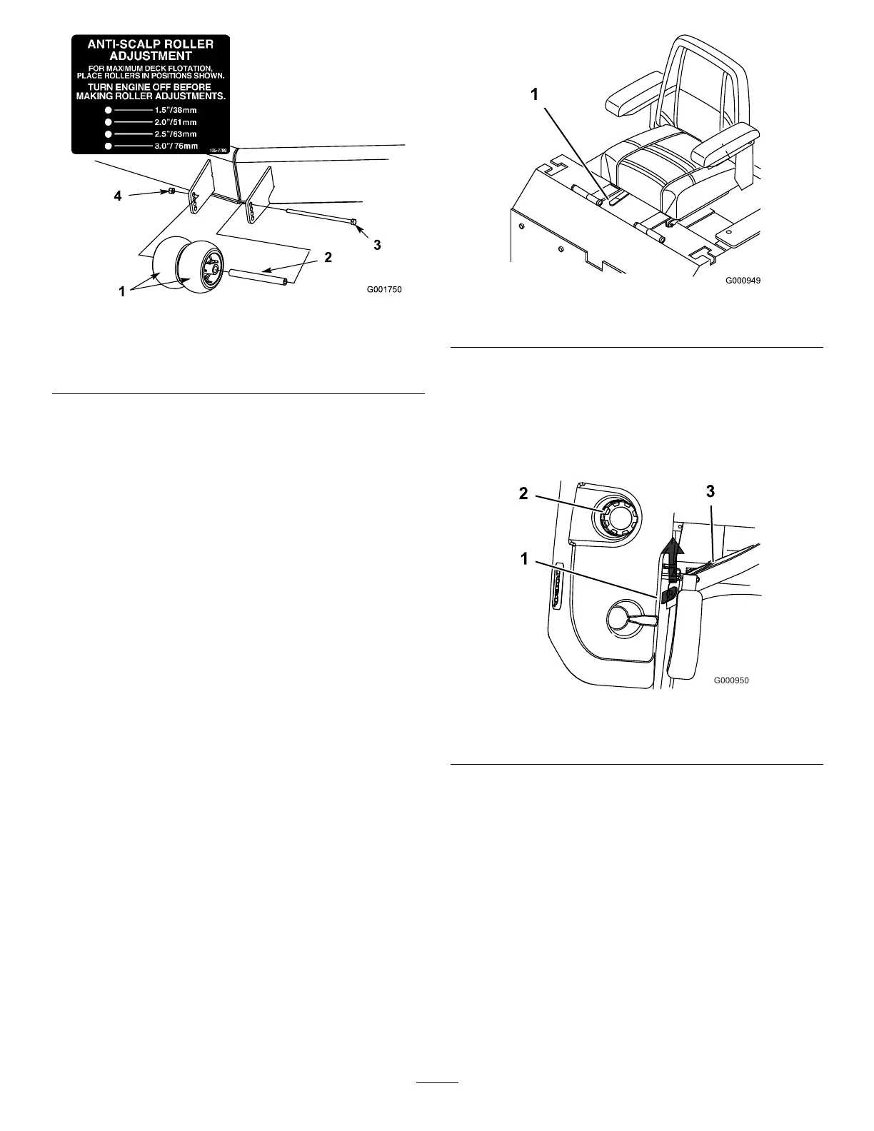
Figure19
1.Outerroller
4.Bolt
2.Spacer
5.Nut
3.Bushing
4.Selectaholesothatthecenterrollersarepositioned
tothenearestcorrespondingheight-of-cutdesired
(Figure19).
Note:Donotadjusttherollerstosupportthe
mowerhousing.
5.Installthecenterrollers,bushing,spacer,bolt,and
nut(Figure19).
6.Torquetheboltto40to45ft-lb(54to61N⋅m).
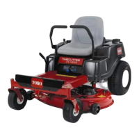
PositioningtheSeat
Theseatcanmoveforwardandbackward.Positionthe
seatwhereyouhavethebestcontrolofthemachine
andaremostcomfortable.
Important:Toadjust,movetheleversidewaysto
unlockseat(Figure20).
Slidetheseattothedesiredpositionandreleaselever
tolockinposition.
Figure20
1.Adjustmentlever
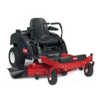
UnlatchingtheSeat
Pushtheseatlatchrearwardtounlatchtheseat.
Thiswillallowaccesstothemachineundertheseat
(Figure21).
Figure21
1.Seatlatch3.Seat
2.Fuelcap
PushingtheMachinebyHand
Important:Alwayspushthemachinebyhand.
Nevertowthemachinebecausehydraulicdamage
mayoccur.
PushingtheMachine
1.Disengagethepowertakeoff(PTO)andturnthe
ignitionkeytooff.Movetheleverstoneutrallocked
positionandapplyparkingbrake.Removethekey.
2.Rotatetheby-passvalvescounterclockwise1turn
topush.Thisallowshydraulicuidtoby-passthe
pumpenablingthewheelstoturn(Figure22).
21