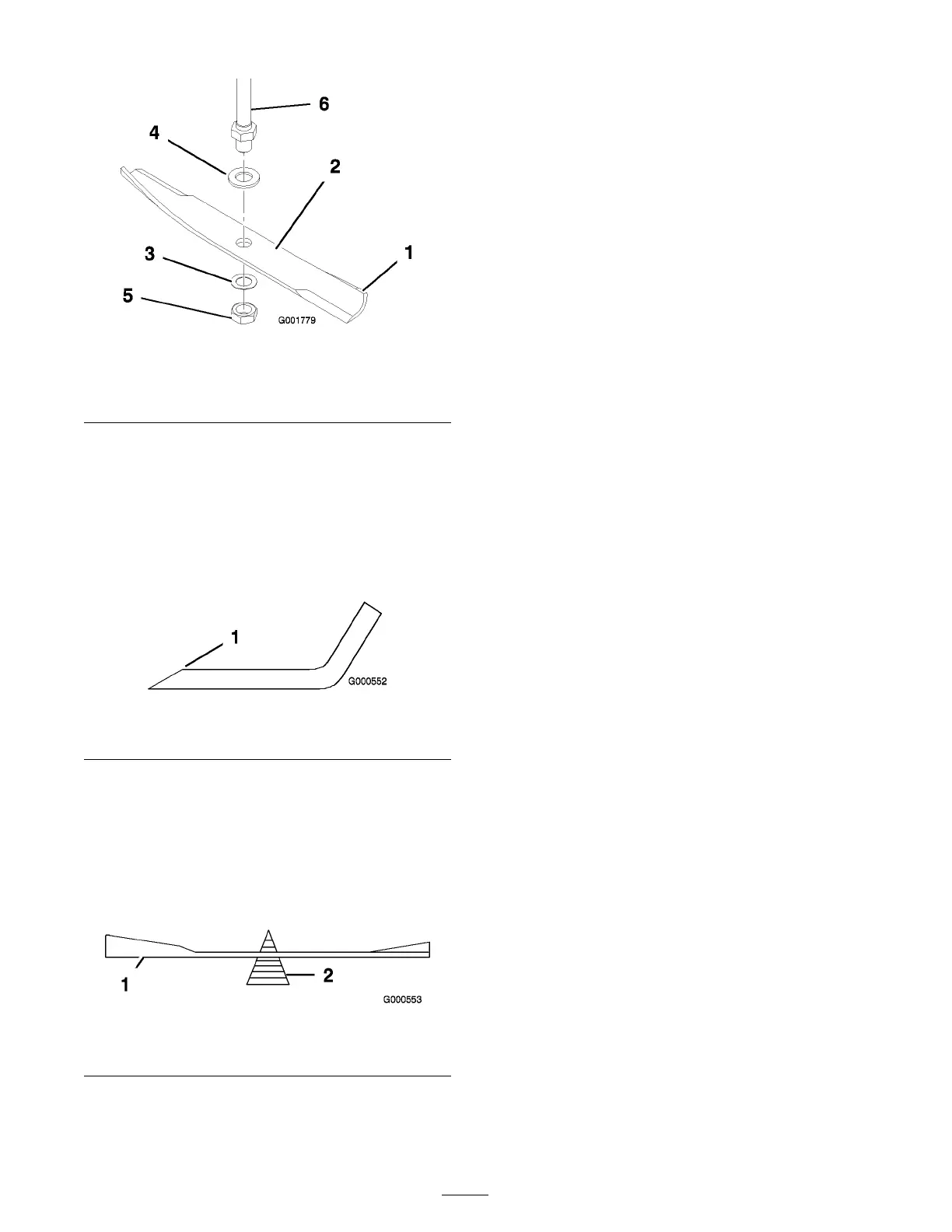
Figure 38
1. Sail area of blade 4. Flat washer, large
2. Blade 5. Blade nut
3. Flat washer, small 6. Spindle shaft
Sharpening the Blades
1. Use a file to shar pen the cutting edg e at both
ends of the blade ( Figure 39 ). Maintain the
original angle . T he blade retains its balance if
the same amount of material is remo v ed from
both cutting edg es .
Figure 39
1. Sharpen at original angle
2. Chec k the balance of the blade b y putting it on
a blade balancer ( Figure 40 ). If the blade sta ys
in a horizontal position, the blade is balanced
and can be used. If the blade is not balanced,
file some metal off the end of the sail area only
( Figure 39 ). R e peat this procedure until the
blade is balanced.
Figure 40
1. Blade 2. Balancer
Installing the Blades
1. Install the larg e flat w asher and the blade onto
the spindle shaft ( Figure 38 ).
Important: T he cur v ed par t of the blade
must be pointing up w ard to w ard the inside
of the mo w er to ensur e pr oper cutting .
2. Install the small flat w asher , and the blade n ut
( Figure 38 ). T or que the blade n ut to 80-100
ft-lb (108-135 N ⋅ m).
Leveling the Mower from
Side-to-Side
T he mo w er blades m ust be lev el from side to side .
Chec k the side-to-side lev el any time y ou install
the mo w er or when y ou see an unev en cut on y our
la wn.
1. P ark the mac hine on a lev el surface and
diseng ag e the blade control switc h.
2. Mo v e the motion control lev ers to the brak e
position, stop the engine , remo v e the k ey , and
w ait for all mo ving par ts to stop before lea ving
the operating position.
3. Chec k the air pressure of all four tires . If
needed, adjust to the recommended inflation;
refer to Chec king the Tire Pressure in
Dri v e System Maintenance , pag e 28 .
4. Set the height-of-cut lev er to position 4
[4 inc h (108 mm)].
5. Carefully rotate the blade(s) side to side
( Figure 41 ). Measure betw een the outside
cutting edg es and the flat surface ( Figure 41 ).
If both measurements are not within 3/16 inc h
(5 mm), an adjustment is required; contin ue
with this procedure .
30