Installing the Mower
1. P ark the mac hine on a lev el surface and
diseng ag e the blade control switc h.
2. Mo v e the motion control lev ers to the brak e
position, stop the engine , remo v e the k ey , and
w ait for all mo ving par ts to stop before lea ving
the operating position.
3. Slide the mo w er under the mac hine .
4. Lo w er the height-of-cut lev er to the lo w est
position.
5. Attac h the adjusting rod to the mac hine with
the w asher and hair pin cotter ( Figure 47 ) on
eac h side of the mo w er .
6. Slide the lev eling brac k ets onto the mounting
pins and secure them with the w ashers and
hair pin cotters ( Figure 47 ).
7. Attac h the front suppor t rods to the mac hine
with the clevis pins and hair pin cotters
( Figure 46 ).
8. Install the mo w er belt onto the engine pulley;
refer to R e placing the Mo w er Belt.
Replacing the Grass
Deector
An unco v er ed discharge opening could
allo w the la wn mo w er to thr o w objects in
the operator’ s or bystander’ s dir ection and
r esult in serious injur y . Also, contact with
the blade could occur .
Nev er operate the la wn mo w er unless y ou
install a co v er plate, a mulch plate, or a g rass
chute and catcher .
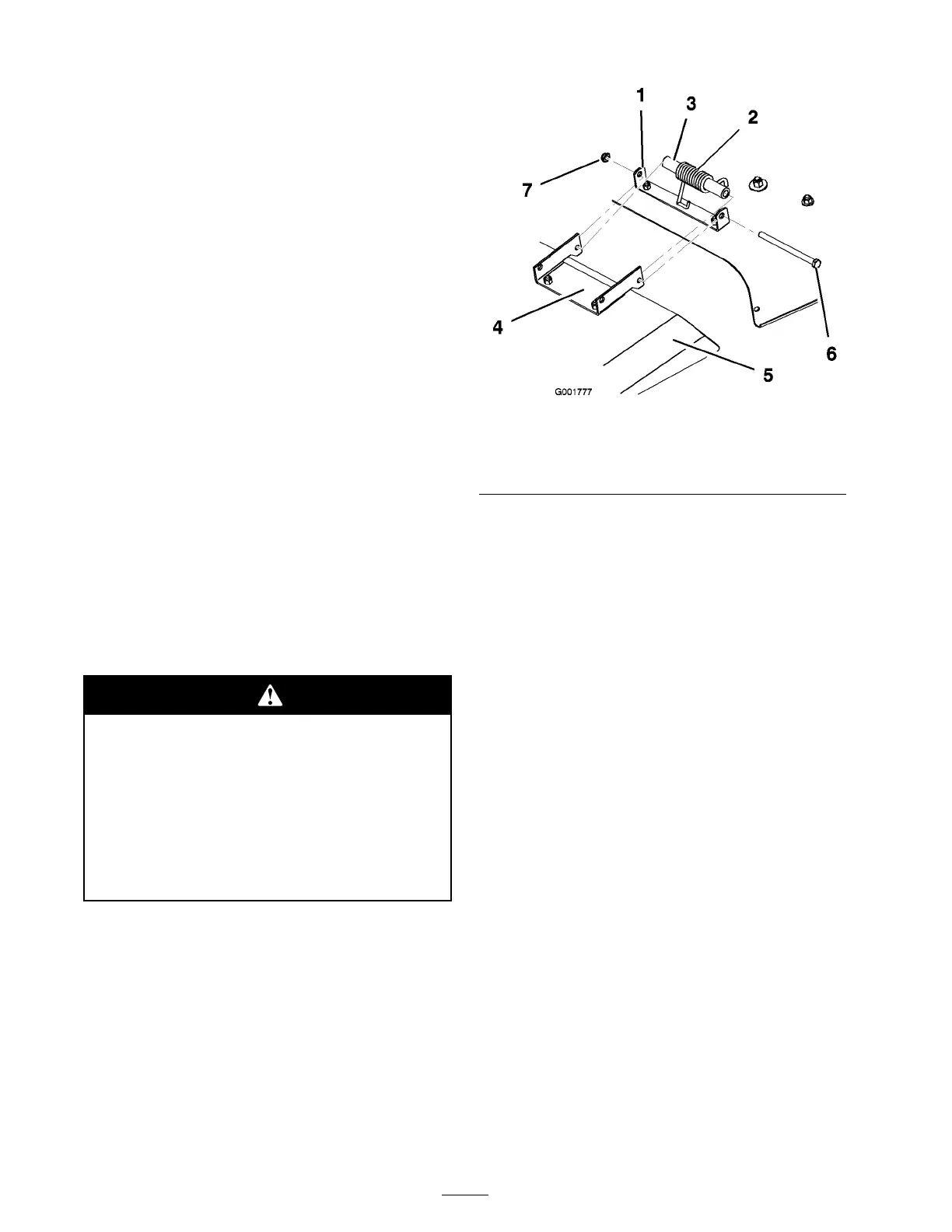
1. R emo v e the loc kn ut, bolt, spacer , and spring
holding the deflector to the mo w er brac k ets
( Figure 49 ). R emo v e the damag ed or w or n
g rass deflector .
Figure 49
1. Mower bracket 4. Grass deector
2. Spring hook end 5. Bolt
3. Space for spring 6. Locknut
2. Align the g rass deflector with the holes in the
brac k ets and the spring and spacer straight
ends in the space betw een the brac k ets and
abo v e the deflector ( Figure 49 ).
3. Place the spring and spacer so that the hook ed
ends of the spring are pointing do wn, with one
end contacting on the mo w er dec k and the
other o v er the deflector ( Figure 49 ).
4. Secure the deflector to the mo w er brac k et with
the bolt. T he bolt should pass through the
g rass deflector , spring, spacer , and brac k ets .
Secure with the loc kn ut.
Note: It ma y be helpful to press do wn near
the end of the bolt with a 9/16 inc h open end
wrenc h to align the bolt with the second hole
on the mo w er brac k et and g rass deflector .
5. Lift the g rass deflector and c hec k that it is
spring loaded and pi v ots freely to the full do wn
position.
Important: T he g rass deflector must be
spring loaded in the do wn position. Lift
the deflector up to test that it snaps to the
full do wn position.
34